Excertos do catálogo

XI'AN YUNYI INSTRUMENT COMPANY LIMITED 1.Pressure Transmi�er 4.Dead Weight Tester 7.Temperature Transmi�er 2.Pressure Guage 5. Level Transmi�er 8.Density Meter
Abrir o catálogo na página 1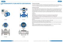
ELECTROMAGNETIC FLOW METER USER MANUAL Product descrip�on YFM Smart electromagne�c flow meter is a high-performance, high-reliability flow meter. It used to measure the volume flow of conduc�ve liquid and slurry in closed pipelines. Widely used in steel, electricity, petroleum, chemical industry, coal, metallurgy, papermaking, water supply and drainage, food, pharmaceu�cal industry, etc. Working principle The measuring principle of electromagne�c flow meter is based on Faraday's law of electromagne�c induc�on. The sensor is mainly composed of a measuring tube with an insula�ng lining, a pair of...
Abrir o catálogo na página 2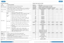
Technical parameter
Abrir o catálogo na página 3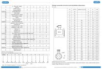
Flange connection structure and installation dimensions Unit: mm Selection codes explanation Model Code: YFM-4800E50DY3MX5B1F1P1RE-L (l)Instrument size error ± 2mm (2) The rated flange pressure of this table DN10-DN300: 1.6MPa DN350-DN500: 1.0MPa ,DN600-DN2200: 0.6MPa. (3)Other flange standards are customized.
Abrir o catálogo na página 4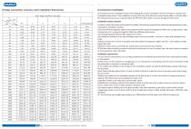
Flow range and Flow rate table Instrument installation Choosing the correct installation location and adopting the correct installation method is the key to using the electromagnetic flow meter. If the installation is wrong, Not only will it affect the measurement effect, it will also affect the measurement accuracy, it will also affect the life of the flow meter, and even damage the flow meter. Installation location selection In order to make the sensor work reliable and stable, the following requirements should be paid attention to when choosing the installation location: (1)Try to avoid...
Abrir o catálogo na página 5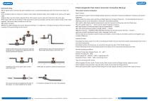
Instrument wiring ●If the signal cable connected by split installa�on uses a customized dedicated cable, the shorter the cable, the be�er. ●The excita�on cable can choose Yz medium-sized rubber sheathed cable, and its length is the same as the signal cable. ●Signal cables must be strictly separated from other power sources and cannot be laid in the same pipe. ●The signal cable and the excita�on cable should be as short as possible, and the excess cables should not be rolled together. The excess cables should be cut off, and ●Re-solder the joints. ●When the cable mediates the sensor...
Abrir o catálogo na página 6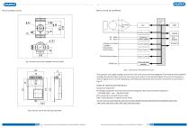
Plot of installing measure exci�ng circuit Switching Power Supply 4-20mA or 0-10mA 1-5000Hz Frequencyor Pulse Output Current Output Pulse Output OC Gate Status Output Fig.1 Exterior size of the integrated Circular shells Status Control Communica�on Interface Fig.2. 1 Structure Of Converter’s Circuit The converter can supply exci�ng current to the coil in the sensor of electromagne�c Flow meter,the head amplifier amplifies the electromo�ve force from the sensor and converts it into standard signals of current or frequency so that the signals can be used for displaying, controlling and...
Abrir o catálogo na página 7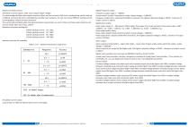
Request of relative sensor Sensitivity of sensor signal: under 1m/s, output 150pV ~200pV; For electromagnetic flow meter signal converters, there are four currents of 62.5mA in exciting loop, which make up of 250mA, and every 62.5mA is controlled by one 20Q exact resistance. So user can choose different exciting current by changing the number of exact resistance. The current will be 250mA when the signal converters leave factory, as such, if there are three exact resistance, the current will be 187.5 mA; if two, 125mA; Resistance of sensor exciting coil: 500mA exciting current: 20 ~ 30Q;...
Abrir o catálogo na página 8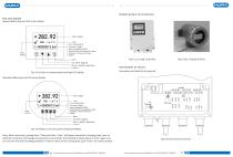
Se c � on p i c t u re of conve rs i on Key a nd d i s p l ay Squared define keys and LCD screen display C on n e c � on s of s e n sor Fig. 4.1 (c) Keys on squared panel and large LCD display: Connectors and labels for the squared Rotundity define keys and LCD screen display Fig. 4.1(d) Keys on Circular panel and big LCD display Note: When measuring, pushing down “Compound Key + Enter” will appear password of changing state, base on dis�nc�on of secrecy, and change the password as we provide. Then pushing “Compound Key + Enter” again, and you can inter the state of se�ng parameter. If want...
Abrir o catálogo na página 9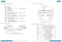
Labels of connectors in squared model Links and labels of connectors in Circular Model SIG 1 Signal 1 SGND Signal Ground SIG2 Signal 2 DS1 Shielded Exciting 1 DS2 Shielded Exciting2 EXT + Exciting Current + EXT- Exciting Current -VDIN Current Two lines 24 V Spots ICOUT Analog Current Output ICCOM Analog Current Output Ground _ POUT Flow Frequency ( Pulse)Output PCOM Frequency (Pulsc)Output Ground ALMH Upper Limit Alarm Output ALM L Low Limit Alarm Output ALCOM Alarm Output Ground _ TCOM 232 Communication Ground To Separate Model Sensor Analog Current Output Frequency (Pulse) Output Two...
Abrir o catálogo na página 10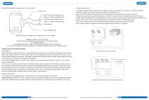
Labels and connec�on of signal lines in Circular model Output and power line All cables for signals transferring and power supply must be prepared by users. However, it should be careful to choose the cables that meet the upper limit load of consuming current. Note: When DIP switch next to terminal is set to ON places, the converter from its inside can provide +28Vpower supply and up-pull 10kΩ resistance to output Frequencies (PUL) to isolated OC gate, Alarm Output (ALMH.ALML), and Status Control ( INSW).Therefore, when converter has frequency output and works with sensor together, DIP...
Abrir o catálogo na página 11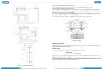
The grounding requirements when installing convert Contact area of copper Connector PE on Converter Cabinet for grounding should be larger than 1.6mm2.Contact resistance should be less than 10Ω. First, purple copper tube should be cut into 1700 mm long (the copper tube can be lengthened according to the need ) to make the nail buried 1500 mm into the ground(Note : when burying nail, sprinkling a layer of broken charcoal at the top of nail, and then saline irriga�on). Then, 4 mm2 purple copper wire should be welded to the nail. At last, connec�ng ground wire to convert’s flange, ground ring...
Abrir o catálogo na página 12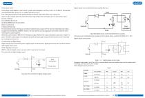
Pulse output mode: Pulse output mainly applies in count mode. A pulse output delegates a unit flux, such as 1L or 1M3 etc. Pulse output unit divide into0.001L, 0.01L, 0.1L, 1L, 0.001m3, 0.01m3, 0.1m3, 1m3 ,0.001UKG,0.01UKG, 0.1UKG,1UKG,0.001USG,0.01USG,0.1USG,1USG .When users choose the pulse unit, they should notice the match of the flux range of flow meter and pulse unit. For volume flux, count formula as follows: QL=0.0007854xD2xV (L/S) Or QM=0.0007854xD2xVx10-3 (M3/S) Note: D-nozzle (mm) V-velocity of flow (m/s) The oversize flux and too small pulse unit will be made the pulse output...
Abrir o catálogo na página 13Todos os catálogos e folhetos técnicos Xi'an Yunyi Instrument Co.
-
 K series
3 Páginas
-
 YX-2006B
2 Páginas
-
 XY-2002
1 Páginas
-
 YFM4800E
14 Páginas
-
 YD32
YD322 Páginas
-
 Relative pressure transmitter YD38
3 Páginas
-
 Temperature calibrator WT
2 Páginas
-
 Bimetallic thermometer WSS series
2 Páginas
-
 Pt100 temperature sensor
3 Páginas
-
 Thermistor temperature sensor
2 Páginas
-
 Pt100 temperature transmitter
3 Páginas
-
 Digital density meter JL-T
6 Páginas
-
 Process density sensor
8 Páginas
-
 Digital density meter YMF883
4 Páginas
-
 Digital density meter JL-YT
4 Páginas
-
 Digital density meter JL-LD
2 Páginas
-
 Digital density meter JL-SD
2 Páginas
-
 Digital density meter JL-GD
2 Páginas
-
 Portable pH meter K series
2 Páginas
-
 Digital density meter YMF-886
5 Páginas
-
 Leak calibrator XY-2006B
2 Páginas
-
 Deadweight tester JY
2 Páginas
-
 Pressure calibrator XY-2001A
2 Páginas
-
 Pressure calibrator YX-60
2 Páginas
-
 Leak calibrator YX-2001C
2 Páginas
-
 Absolute pressure gauge YK-100
2 Páginas
-
 Dial pressure gauge YK-M3 series
3 Páginas
-
 Dial pressure gauge YK-M4
2 Páginas
-
 Differential pressure gauge YK-M2
3 Páginas
-
 Absolute pressure gauge YK-120B
2 Páginas
-
 Absolute pressure gauge YK-80
2 Páginas
-
 Absolute pressure gauge YK-100B
2 Páginas
-
 Pressure gauge with LCD display YK60
2 Páginas
-
 Electromagnetic flow meter YFM3800
3 Páginas
-
 Mass flow meter YFU2000-B
4 Páginas
-
 Ultrasonic flow meter TUF-2000H
4 Páginas
-
 Ultrasonic flow meter HK-G4-G6-G10
8 Páginas
-
 Mass flow meter Coriolis
14 Páginas
-
 Orifice flow meter
6 Páginas
-
 Mass flow meter MF4000
3 Páginas
-
 Mass flow meter
3 Páginas
-
 Ultrasonic flow meter YFU2000-B
4 Páginas
-
 Vortex flow meter YFV
20 Páginas
-
 Ultrasonic flow meter YFU2000H
14 Páginas
-
 Turbine flow meter YFT
13 Páginas
-
 Mass flow meter YFV300
20 Páginas
-
 Mass flow meter YFT300D
13 Páginas
-
 Turbine flow meter
13 Páginas
-
 Mass flow meter MF5700
3 Páginas
-
 Radar level transmitter YUNYI-806A3
14 Páginas
-
 Ultrasonic level transmitter MH-A
11 Páginas
-
 Liquids level gauge UHZ-10
1 Páginas
-
 Radar level transmitter YUNYI-806A4
14 Páginas
-
 Level measuring instrument
11 Páginas
-
 Liquids level gauge YLR68
12 Páginas
-
 Liquids level gauge YR80G series
5 Páginas
-
 Liquids level gauge
3 Páginas
-
 Piezoresistive level sensor YLT325
4 Páginas
-
 Radar level sensor
12 Páginas
-
 Piezoresistive level transmitter
4 Páginas
-
 Absolute pressure transmitter YD32-S
4 Páginas
-
 Relative pressure transmitter YD33
4 Páginas
-
 Absolute pressure transmitter YD34
4 Páginas
-
 Absolute pressure transmitter YD37
4 Páginas
-
 Diaphragm pressure switch
2 Páginas
-
 Digital pressure controller
2 Páginas
-
 Absolute pressure transmitter YD-323
2 Páginas
-
 Relative pressure transmitter
2 Páginas
-
 Explosion-proof pressure transmitter
2 Páginas
-
 YD31 series
4 Páginas