Excertos do catálogo
VTdrive - Harmonic Distortion from Variable Speed Drives
Abrir o catálogo na página 1
Introduction to Harmonics Symptoms Expected Harmonics from VFD’s Harmonic Resonance Understanding IEEE519-1992 Harmonic Solutions for VFD’s
Abrir o catálogo na página 2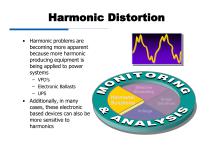
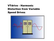
Harmonic Distortion • Harmonic problems are becoming more apparent because more harmonic producing equipment is being applied to power systems – VFD’s – Electronic Ballasts – UPS • Additionally, in many cases, these electronic based devices can also be more sensitive to harmonics Effective Grounding Harmonic Solutions Surge Solutions Voltage Variation Solutions
Abrir o catálogo na página 3
problem unless they are a Horizontal 2500 microseconds/digision Vertical 500 Uolts/division Urns: Preu=610.7, Min=605.5, Max=605.5 - Uorst Inp= H Upk, 0 deg
Abrir o catálogo na página 4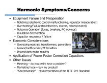
Harmonic Symptoms/Concerns • Equipment Failure and Misoperation – – – – – Notching (electronic control malfunctioning, regulator misoperation) Overheating/Failure (transformers, motors, cables/neutral) Nuisance Operation (fuses, breakers, PC lock-ups) Insulation deterioration Capacitor resonance / failure • Economic Considerations – Oversizing neutrals, transformers, generators – Losses/Inefficiencies/PF Penalties – Inconsistent meter reading • Application of Power Factor Correction Capacitors • Other Issues – Metering – do you really have a problem? – Marketing hype – buy my product! –...
Abrir o catálogo na página 5
Expected Harmonics Source Typical Harmonics* Arcing Devices Transformer Energization * Generally, magnitude decreases as harmonic order increases
Abrir o catálogo na página 6
Harmonic Spectrum Harmonic magnitude (per unit) 0.2 0.14 • Normal VFD Harmonic Spectrum – Lower harmonic orders have the higher magnitudes – Magnitudes should decline as the harmonic order increases
Abrir o catálogo na página 7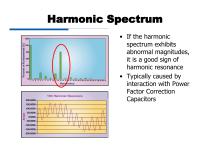
Harmonic Spectrum spectrum exhibits abnormal magnitudes, harmonic resonance interaction with Power Factor Correction
Abrir o catálogo na página 8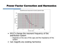
Power Factor Correction and Harmonics Parallel Resonant Frequencies for Various Capacitor Sizes Harmonic Order • PFCC's change the resonant frequency of the distribution system - Depends on the size of the caps and the impedance of the • Can magnify any existing harmonics
Abrir o catálogo na página 9
Power Factor Correction and Harmonics HARMONIC NUMBER Reactors can be added to the PFCC bank to create a tuned filter - Tuned to a 'non-characteristic' harmonic (i.e. 4.7th) Becomes a sink for 5th harmonic currents
Abrir o catálogo na página 10
IEEE 519 - 1992 • It is currently the only recognized industry standard in North America for setting harmonic limits (voltage and current) • Designed to limit utility harmonics as well as customer harmonic contribution to the utility grid • Standard ONLY applies to the Point of Common Coupling (PCC) – The point where the utility connects to multiple customers – If a utility transformer is provided, the PCC is most likely on the LINE side of the transformer IEEE 519 is widely misunderstood and misapplied in the industry
Abrir o catálogo na página 11
IEEE 519 – Point of Common Coupling (PCC) Possible POA’s (Customer Side) (Utility Side) Only place that IEEE 519 applies ??? = Linear loads for % current distortion dilution
Abrir o catálogo na página 12
Harmonic Calculators File Help General System Special Applications XFMR Filter Total HP of Linear Load
Abrir o catálogo na página 13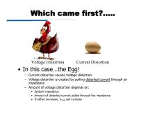
Which came first?….. Voltage Distortion Current Distortion • In this case…the Egg! – Current distortion causes Voltage distortion – Voltage distortion is created by pulling distorted current through an impedance – Amount of voltage distortion depends on: • System impedance • Amount of distorted current pulled through the impedance • If either increases, VTHD will increase
Abrir o catálogo na página 14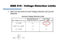
IEEE 519 - Voltage Distortion Limits IEEE 519 sets limits for both Voltage distortion and Current Harmonic Voltage Distortion Limits
Abrir o catálogo na página 15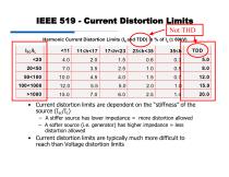
IEEE 519 - Current Distortion Limits Not THD Harmonic Current Distortion Limits (Ih and TDD) in % of IL (≤ 69kV) • Current distortion limits are dependent on the “stiffness” of the source (Isc/IL) – A stiffer source has lower impedance = more distortion allowed – A softer source (i.e. generator) has higher impedance = less distortion allowed • Current distortion limits are typically much more difficult to reach than Voltage distortion limits
Abrir o catálogo na página 16
THD vs. TDD • THD(I)= Total Harmonic Current Distortion – Measured distortion on actual instantaneous current flowing – “Sinewave Quality Factor” • Lower the % THD, the closer the current waveform is to a true sinewave – Not used anywhere in IEEE 519 THD = 80% Is this acceptable? Depends on system full load, % linear load, etc.
Abrir o catálogo na página 17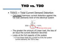
THD vs. TDD • TDD(I) = Total Current Demand Distortion – Calculated harmonic current distortion against the full load (demand) level of the electrical system Full load of the system – The greater the amount of Linear load, the less of an issue the current distortion becomes – Looks at the full capacity of the system • If non-linear loads are a small % of the full system current demand, the TDD is less
Abrir o catálogo na página 18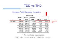
TDD vs THD Example: With Harmonic Correction Full load * As the load decreases, TDD decreases while THD(I) increases. Equal at full load
Abrir o catálogo na página 19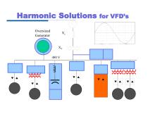
Harmonic Solutions for VFD’s Oversized Generator Active Filter Blocking Filter Isolation Transformer Tuned Filter Phase Shift Transformers
Abrir o catálogo na página 20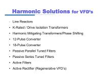
Harmonic Solutions for VFD’s * Line Reactors • K-Rated / Drive Isolation Transformers • Harmonic Mitigating Transformers/Phase Shifting • 12-Pulse Converter • 18-Pulse Converter • Passive Parallel Tuned Filters • Passive Series Tuned Filters • Active Filters • Active Rectifier (Regenerative VFD’s)
Abrir o catálogo na página 21
Line Reactors • Line Reactor = Inductor • An inductor slows down the rate of rise of current. Current • Impedance of an inductor increases as frequency increases • Reactors have more impedance the higher the harmonic order
Abrir o catálogo na página 22
Effect of Drive Line Reactors
Abrir o catálogo na página 23Todos os catálogos e folhetos técnicos VTDRIVssE Technology Limited
-
 Brake unit FWI-BU3 series
1 Páginas
-
 VP5 Constant pressure water supply
3 Páginas
-
 VS5 Solar pump inverter
3 Páginas
-
 VTdrive FIT-Closed Loop VFD for Industrial
276 Páginas
-
 VTdrive Line Reactors and AC Drives
6 Páginas
-
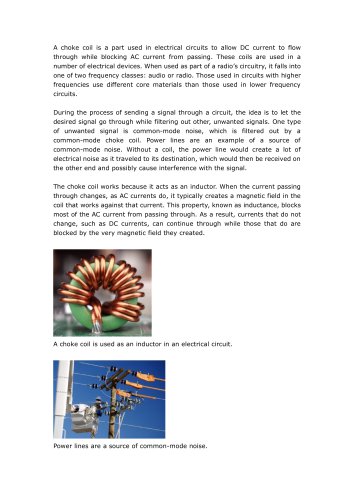 VTdrive What is a Choke Coil
2 Páginas
-
 VTdrive What is VFD Line Reactor
2 Páginas
-
 VTdrive Reactive Power Compensation
4 Páginas