Excertos do catálogo

100% Made & Designed in Italy POWER & ENERGY MONITORING SYSTEM
Abrir o catálogo na página 1
1. POWER METERS AND ROGOWSKI COILS 1.4. Rc150 Series - Rogowsi coils 8 2.1. S500 Series - Technical data 10 2.2. S500 Series - Programming system 12 SENECA I Power & Energy Monitoring System
Abrir o catálogo na página 2
Serie S604 / S711 MULTIFUNCTION POWER METERS (STANDARD AND COMPACT VERSIONS) S604 and S711 Series are instruments for the measurement and storage of electrical parameters. They are particularly suitable when a device for analysis and control is required consumption, with an excellent price/performance ratio. Rogowski current transducers versions offer extreme ease of connection and can be used in applications with high currents, linear measurements, retrofitting, energy audits etc. On request, the tools can communicate through the RS485 serial port with ModBUS RtU/ASCII protocol or via...
Abrir o catálogo na página 3
! Power Meter ENERGY Plus version GENERAL DATA Power supply Serial Port Voltage Input PROGRAMMING Configuration systems Technical data, diagrams and drawings in this catalog are indicative only and not binding SENECA I Power & Energy Monitoring System
Abrir o catálogo na página 4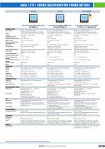
Three-phase Power Meter BASIC version, DIN 96x96 mm Three-phase Power Meter ENERGY Plus version, DIN 96x96 mm Threee-phase power meter kit including nr.1 S711B + nr. 3 Rogowski coils COMMUNICATION Serial Port Voltage Input MEASUREMENT INPUT Current Input Digital Output Analog Output PROGRAMMING Max voltage: 600 Vac max L-L 20/35 VCA (* VT ratio, using VT) Input impedance: >1,3 MOhm Frequency: 45 -65 Hz Max nominal value: 7 A Starting current (1st): 2 mA CT load: max 0,15 VA per phase Min FFT calculation value: 100 mA * CT ratio Max voltage: 600 Vac max L-L 20/35 VCA (* VT ratio, using VT)...
Abrir o catálogo na página 5
FRONT KEY BUTTONS Readings, settings and recording are available through tramite front key buttons with 7 display page groups management. Configuration tool for Energy power meters SERVER S604B and S604E. ENERGY POWER PACK assures reading and visualization of all measurements, it also provides a overall setup of parameters, downloading and converting recording and it manages remote connections By Web Server it’s possible visualizing all device values and associate a recording exportabla into a csv file ORDER CODES Code Descrii POWER METERS Three phase power meter, BASIC version, for CT/5A,...
Abrir o catálogo na página 6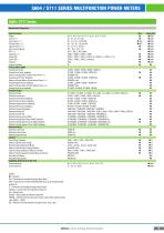
Measurement Parameters LEGEND • = Standard AVG = Parameters for recording of average values (fixed) MAM = Parameters for recordin of MIN/AVG/MAX values (up to 24 programmable parameters) EC = Parameters for recording of energy counters (fixed) imp&exp = Separate values for imported and exported abs = Absolute value ind&cap = Valori separati per induttivo e capacitivo DMDBAL = Difference between the positive average value and the negative average value: [DMD+] - [DMD-] BAL = Difference between imported and exported value: [imp] - [exp]
Abrir o catálogo na página 7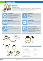
ROGOWSKI COILS ROGOWSKI COILS An air-cored toroidal winding is placed around the conductor, the magnetic field produced by the current induces in the coil a voltage proportional to the rate of change of current. Integrating this voltage the output become proportional to the current (as for a current transformer). Coil length variates from 25 to 300 cm for a cord diameter up to 8 mm • The junction point is insensitive to both the position of the internal conductor and to currents carried by external conductors • Coil and cable shielded against electromagnetic noise • Cross section reduced up...
Abrir o catálogo na página 8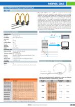
HIGH PERFORMANCE ROGOWSKI COILS Rogowski coils have been used for the detection and measurement of electric currents for decades. They are based on a simple principle where an “air-cored” coil is placed around the conductor in a toroidal fashion and the magnetic field produced by the current induces a voltage in the coil. The voltage output is proportional to the rate of change of current. This voltage is integrated, thus producing an output proportional to the current. By using precision winding techniques, especially developed for the purpose, the coils are manufactured so that their...
Abrir o catálogo na página 9
ENERGY COUNTERS - S500 SERIES S500 Series ENERGY COUNTERS The new SENECA energy counters for DIN rail mounting cover the most different application requirements for single-phase and threephase systems. Available with RS485 Modbus, M-BUS or Ethernet + webserver communication interfaces, the energy counters are compliant with MID (2004/22 / EC Directive) in class B with EN 50470 standard. Equipped with Wide backlighted LCD display for easy consultation of the values of energy and power, the counters also make avalilable the diagnostic function signaling polarity errors in the connection....
Abrir o catálogo na página 10
Single phase energy counter 2 wires 1 DIN, MID certified Single phase energy counter 2 wires 2 DIN Three phase energy counter 4 wires 4 DIN, built-in communication, MID certified Three phase energy counter 3/4 wires 4 DIN, MID certified GENERAL DATA Nominal Values Protocols supported Programming System Front key button E-MODBUS-PACK, E-MBUS-PACK Front key buttons Front key buttons E-MODBUS-PACK, E-MBUS-PACK E-MODBUS-PACK, E-MBUS-PACK Front key buttons E-MODBUS-PACK, E-MBUS-PACK Power Supply SENECA I Power & Energy Monitoring System
Abrir o catálogo na página 11
FRONT KEY BUTTONS By f ront key buttons on all models can be programmed these • Page scroll Temporary visualization of secondary values ^ • Access / exit Programming pages • Start / stop / reset partial hour counter • Setting parameters • Display test All counters S500 Series energy counters - Ethernet or external COM version -have access to a WEB SERVER accessible through protected connection. WEB SERVER prov ides real-time values and recorded data in .csv exportable files. ENERGY MODBUS PACK ENERGY M-BUS PACK Modbus models can be configured through sof tware package ENERGY MODBUS PACK...
Abrir o catálogo na página 12
Measuring parameters Symbol UM/Status Display COM port Instantaneous values Voltage Current Power factor Active power Apparent power Reactive power Frequency Power direction Stored data Inductive and capacitive apparent energy kVAh ■ Inductive and capacitive reactive energy kvarh ■ 0 Resettable energy meters (NO MID) kWh, kVAh, kvarh ■ 0 Resettable partial energy counters kWh, kVAh, kvarh ■ 0 Other information Status of partial counters P Started / Stopped • • Output status S0 • Active • Measuring parameters Symbol UM/Status Display COM port Instantaneous values Voltage Current Power factor...
Abrir o catálogo na página 13Todos os catálogos e folhetos técnicos SENECA | AUTOMATION INTERFACES
-
 T201 SERIES AC/DC CURRENT TRANSDUCERS
16 Páginas
-
 SSD SURPRISE SMART DISPLAY
16 Páginas
-
 R-PASS Industrial IoT Edge Gateways
4 Páginas
-
 Z-D-IN
1 Páginas
-
 Z-LINE MULTISTANDARD SIGNAL CONVERTERS
16 Páginas
-
 IoT ADVANCED GATEWAYS
8 Páginas
-
 Z-LTE
Z-LTE2 Páginas
-
 DATA RECORDER
8 Páginas
-
 Z-KEY-WIFI
2 Páginas
-
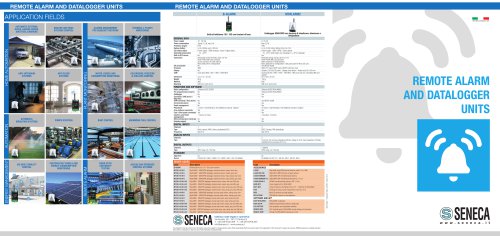 Remote Alarm and Datalogger Units
2 Páginas
-
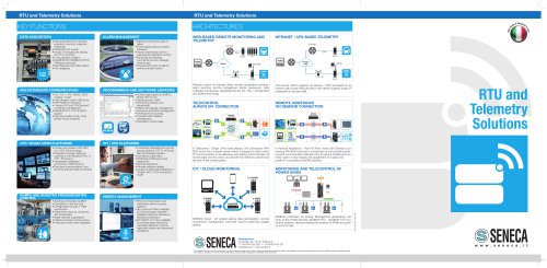 RTUs and Telemetry Solutions
2 Páginas
-
 S203 Series Energy Power Meters
4 Páginas
-
 S401 OLED ModBUS Display
2 Páginas
-
 Advanced dataloggers
6 Páginas
-
 LETS - IoT Connectivity Solutions
6 Páginas
-
 K Line Compact Converters
8 Páginas
-
 Fiber Optic converters
4 Páginas


Catálogos arquivados
-
 S401
S4012 Páginas
-
 AUTOMATION NTERFACES GENERAL CATALOG
212 Páginas
-
 Energy Efficiency
8 Páginas
-
 Distributed automation and Telecontrol
12 Páginas
-
 Universal Converter
2 Páginas
-
 A converter...really universal!
9 Páginas
-
 Ultra slim line converters
2 Páginas
-
 USB to serial Universal Converter
2 Páginas
-
 Distributed systems
2 Páginas
-
 ModBUS Display
1 Páginas
-
 Photovoltaic Systems
2 Páginas
-
 Loop powered display
2 Páginas