
Excertos do catálogo

OPTICAL SPEED AND LENGTH SENSORS ISD-3+ Series User's manual www.riftek.com info@riftek.com
Abrir o catálogo na página 1
Optical Speed And Length Sensors. ISD-3+ Series
Abrir o catálogo na página 2
Optical Speed And Length Sensors. ISD-3+ Series Safety precautions · Use supply voltage and interfaces indicated in the sensor specifications. · In connection/disconnection of cables, the sensor power must be switched off. The sensors have been developed for use in industry and meet the requirements of the following Directives: · EU directive 2014/30/EU. Electromagnetic compatibility (EMC). · EU directive 2011/65/EU, “RoHS“ category 9. General information Currently, the ISD-3 family includes 6 models with different versions with the working range from 10 cm to 80 cm (available on request)....
Abrir o catálogo na página 3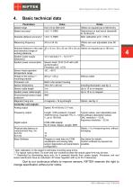
Optical Speed And Length Sensors. ISD-3+ Series Basic technical data Parameters Speed range Speed accuracy* Absolute distance accuracy* <±0.1 % RMS Measuring frequency Notes Others on request (up to 500 km/h). Determined on test bench (treadmill) at 18.38 km/h. After calibration at S > 100 m. Others are user adjustable (max 80 Hz). Nominal distance to the road 35 ± 15 cm, 50 ± 20 cm, 80 ± 25 cm Others on request (up to 180 cm). and tolerance (range of ** working distance) System power supply 12 V nominal (11 – 14.5 V)*** (tolerance) System power consumption Sensor head: 20 W (5 W with LED...
Abrir o catálogo na página 4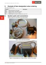
Optical Speed And Length Sensors. ISD-3+ Series Example of item designation when ordering Description Nominal distance to the object Digital interface, COM-USB converter Pulse out: 0-12 V, 0-5 V, or 0-24V Cable length from sensor to controller unit, up to 15 m System parts and connections System parts and connections are shown below. Figure 1. Sensor parts and connectors. Figure 2. Communication unit. “Reset to factory”, see par. 8.3 for details.
Abrir o catálogo na página 5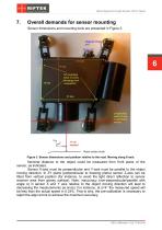
Optical Speed And Length Sensors. ISD-3+ Series Overall demands for sensor mounting Sensor dimensions and mounting tools are presented in Figure 3. Figure 3. Sensor dimensions and position relative to the road. Moving along X-axis. Nominal distance to the object could be measured from front plane of the sensor, as indicated. Sensor X-axis must be perpendicular and Y-axis must be parallel to the object moving direction. In ZY plane (perpendicular to drawing plane) sensor Z-axis can be tilted from vertical position (for instance, to avoid the light direct reflection to sensor receiver area...
Abrir o catálogo na página 6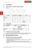
Optical Speed And Length Sensors. ISD-3+ Series Sensor cable: 7 pin FQ14-7T-type to DB9-M Cable view: Pulse output Other cables Destination COM-USB converter Pulce output Power Comments To connect to PC, 115200, 8n1 Black – GND White – Rx Green - Tx 0 – 12V, Rout=1,5K Standard type Controller reset to factory settings In case of any problems, controller can be reset to factory settings. Press the button by some stick, then power ON the system. Factory settings are restored. Working with the sensor Working with the external (custom) DAQ · Fix the sensor properly relative to the object. ·...
Abrir o catálogo na página 7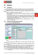
Optical Speed And Length Sensors. ISD-3+ Series The COM-USB cable is used for connection to PC to set up sensor parameters, view signals quality for sensor position adjustment, view and save measurement data. Operating systems: from Windows XP to Windows 10 (different drivers may be needed). What to be installed for program functionality: · Run-Time Engine for support LabView *exe programs. Run Setup in directory “ISD Installer”. · LV Visa to get access to PC ports, including COM. For Windows <7, install visa320runtime. For Windows 7 and later, install visa540_runtime. Note: Only one...
Abrir o catálogo na página 8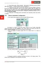
Optical Speed And Length Sensors. ISD-3+ Series 6 – Save Data button. When pressed – data saves in operating memory (RAM), after Stop Program – it writes all data to the file, specified in 7. 7 – Directory and file name to save data. Directory must be created in advance, file will be created automatically, edit the name before program Start. By default, the date and time are added to the name. Known issues here: If the PC data format is like 02/10/2018, the file will not be saved. Change the date-time format in PC or uncheck date-time adding. 8 – Setup tab. To manage sensor parameters and...
Abrir o catálogo na página 9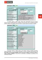
Optical Speed And Length Sensors. ISD-3+ Series 10 1-st Send: sensor in Data mode. Along with measurement data, the sensor sends an array of signal spectrum, it appears in the Test tab. Use it to adjust the sensor position relative to the object to get the maximum signal quality (see below in details). 2-nd Send: sensor in Setup mode. In the picture: result of sending command “Read Parameters”. You see actual parameters in sensor controller Flash memory (at first read, it is the factory defaults, save it as text or picture in the PC to have a copy of factory defaults). The full list of...
Abrir o catálogo na página 10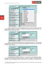
Optical Speed And Length Sensors. ISD-3+ Series List of Commands. First, edit the parameter value you want to change (in the left column (default values, they appear as default at first program Run), then send it by appropriate Command one by one: Result of sending the command. Now the parameter value is in the operating memory of the sensor controller. Change other parameters if needed, then write it to the controller Flash memory: All parameters are written to Flash. You can check it by the Read Parameters command. Then change the Mode to “Data” – sensor is ready for measuring. Note:...
Abrir o catálogo na página 11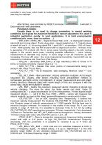
Optical Speed And Length Sensors. ISD-3+ Series controller is very busy, which leads to reducing the measurement frequency and some data may be distorted. After Writing, reset controller by RESET command . It will start in Data mode with new parameters. Parameters details: Usually there is no need to change parameters in normal working conditions, but it gives the maximum flexibility in sensor adjustment. It is used in industrial application mostly. In road applications, it is hard environmental conditions (rain, snow, clear ice surface, …). - SNR_LIM1 и SNR_LIM2 – Signal to Noise Ratio...
Abrir o catálogo na página 12Todos os catálogos e folhetos técnicos RIFTEK EUROPE
-
 PRODUCT CATALOG 2025
44 Páginas
-
 RF603 Series Manual
49 Páginas
-
 RF602 Series Manual
33 Páginas
-
 RF603HS Series Manual
36 Páginas
-
 RF609 (RF609Rt) Series Manual
33 Páginas
-
 RF600 Series Manual
46 Páginas
-
 RF605 Series Manual
29 Páginas
-
 RF60i Series Manual
46 Páginas
-
 RF62x Manual
174 Páginas
-
 RF25x Series Manual
34 Páginas
-
 RF651 Series Manual
32 Páginas
-
 RF656 Series Manual
32 Páginas
-
 RF656XY Series Manual
33 Páginas
-
 RF656.2D, RF657.2D, RF657R.2D Series Manual
104 Páginas
-
 Laser probes Manual
14 Páginas
-
 Pipe ID Control System Manual
18 Páginas
-
 Width Measurement System RF590 Manual
21 Páginas
-
 Edge Sensor RF659 Series Manual
25 Páginas
-
 RF627Smart-Weld manual
103 Páginas
-
 PRODUCT CATALOG 2024
40 Páginas


