
Excertos do catálogo

BiM3H transceiver UHF FM 400mW transceiver module The BIM3H is a miniature PCB mounting UHF radio data transceiver incorporating a received signal strength indicator (RSSI). It allows the simple implementation of data links at speeds up to 10kbps and distances up 5000 metres over open ground. Designed to comply with harmonised radio standard EN 300 220-3 Designed to comply with harmonised EMC standard EN 301 489-3 Data rates up to 10kb/s Usable range up to 5000m Frequency 869.50MHz Fully screened Fast data settling time Available for operation at 869.50MHz in the UK and Europe, the BiM3H combines full screening with internal filtering to ensure EMC compliance by minimising spurious radiation and susceptibility. The module suits one-to-one and multi-node wireless links in applications including car and building security, EPOS and inventory tracking, remote industrial process monitoring and computer networking. Because of the small size and low power requirements, the BIM3H is ideal for use in portable, battery-powered applications such as hand-held terminals. Technical Summary Receiver Single conversion FM superhet SAW front end filter gives >50dB image rejection 5 volt operation Current consumption 15mA -108dBm sensitivity @ 1ppm BER RSSI output with 50dB range Extremely low LO leakage, -125dBm typical Transmitter Transmit power: 400mW (26dBm, +/- 1dB) Operating frequency 869.50MHz 5 volt operation Current consumption 310mA (typical) Data rate: 10 kbps Evaluation platforms: NBEK + BiM / SMX carrier Radiometrix Ltd, BiM3H Data Sheet
Abrir o catálogo na página 1
00 Radiometrix Ltd, BiM3H Data Sheet page 2
Abrir o catálogo na página 2
side view (through can) side view (with can) pin pitch: 2.54 mm recommended PCB hole size: 1.2 mm pins 4, 5, 6, 7 & 8 are not fitted module footprint size: 25 x 32 mm Figure 3: BiM3H Footprint (Top) view Pin description RF IN / OUT (pin 2) 50U input from the antenna, DC isolated. RF GND (pin 1/3) RF ground pin, internally connected to the module screen . This pin should be connected to the RF return path (coax braid, main PCB ground plane etc.) 0V (pin 9/18/10) DC supply ground. Internally connected to pin 2 and module screen. RSSI (pin 11) Received signal strength indicator...
Abrir o catálogo na página 3
Absolute maximum ratings Exceeding the values given below may cause permanent damage to the module. Operating temperature -20 uC to +70 uC RSSI, AF, RXD (pins 11,13,12) -0.1V to +3V RF IN/OUT (pin 2) U50V DC, +10dBm RF (Vcc = 5.0V/ temperature = 200 C unless stated) Baseband Baseband bandwidth @ -3dB 13 0.1 Load capacitance, AFout/RXD - DYNAMIC TIMING Power up with signal present Power up to valid RSSI - Power up to stable data - Signal applied with supply on RSSI response time (rise/fall) 11 - Signal to stable data 12 - Time between data transitions 70...
Abrir o catálogo na página 4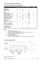
DC supply Supply voltage Supply current RF RF power output Spurious emissions,<1GHz Spurious emissions,>1GHz RF centre frequency Initial frequency accuracy Overal frequency accuracy FM deviation (peak) Antenna impedance Baseband Baseband bandwidth @ -3dB Maximum raw data rate TXD input level (logic low) TXD input level (logic high) DYNAMIC TIMING TX enable to full RF Measured into 50 Ohm load Meets EN requirements at all frequencies There is a <10% duty cycle restriction on 869.50MHz in EU member states Total over full supply and temperature range With 0V - 5V modulation input 5V CMOS...
Abrir o catálogo na página 5
Received Signal Strength Indicator (RSSI) The module incorporates a wide range RSSI which measures the strength of an incoming signal over a range of approximately 50dB. This allows assessment of link quality and available margin and is useful when performing range tests. The output on pin 11 of the module has a standing DC bias in the region of 0.5V with no signal, rising to around 1V at maximum indication. The RSSI output source impedance is high (~100k ) and external loading should therefore be kept to a minimum. To ensure a fast response the RSSI has limited internal decoupling of 1nF...
Abrir o catálogo na página 6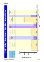
Radiometrix Ltd, BiM3H Data Sheet Duty Cycle Channel Spacing Social Alarm Alarm CEPT/ERC Rec 70-03, 868 MHz Band Plan
Abrir o catálogo na página 7
Copyright notice This product data sheet is the original work and copyrighted property of Radiometrix Ltd. Reproduction in whole or in part must give clear acknowledgement to the copyright owner. Limitation of liability The information furnished by Radiometrix Ltd is believed to be accurate and reliable. Radiometrix Ltd reserves the right to make changes or improvements in the design, specification or manufacture of its subassembly products without notice. Radiometrix Ltd does not assume any liability arising from the application or use of any product or circuit described herein, nor for...
Abrir o catálogo na página 8Todos os catálogos e folhetos técnicos Radiometrix
-
 LNM2H
LNM2H13 Páginas
-
 NiM1B
NiM1B13 Páginas
-
 VX2M
VX2M9 Páginas
-
 WRX2C
WRX2C9 Páginas
-
 MSR3
MSR38 Páginas
-
 LMR0
LMR010 Páginas
-
 SAT3
SAT35 Páginas
-
 NTX2B
NTX2B13 Páginas
-
 NTX0
NTX08 Páginas
-
 MTX3
MTX310 Páginas
-
 MTX2
MTX210 Páginas
-
 QPX1
QPX18 Páginas
-
 QPT1
QPT18 Páginas
-
 AiM1
AiM19 Páginas
-
 Universal Evaluation Kit
27 Páginas
-
 TDL2A Evaluation Kit
4 Páginas
-
 SPM2/RPM Evaluation Kit
7 Páginas
-
 SP2 Evaluation Kit
12 Páginas
-
 NBEK Controller As 1200 Baud Modem
7 Páginas
-
 Narrow Band Module Evaluation Kit
10 Páginas
-
 M48A Application Board
12 Páginas
-
 M1144
M11448 Páginas
-
 DXT / DXR
7 Páginas
-
 Control44 Evaluation Kit
7 Páginas
-
 CTA88 Remote Control Application Boards
16 Páginas
-
 CTA28 App. boards
11 Páginas
-
 BL118
BL1187 Páginas
-
 BD118
BD1185 Páginas
-
 PAN1311
2 Páginas
-
 PAN1310
2 Páginas
-
 m48a
m48a11 Páginas
-
 LMR2
LMR211 Páginas
-
 TDL3F
TDL3F10 Páginas
-
 krx2
krx29 Páginas
-
 KTX2
KTX28 Páginas
-
 RPM3
RPM315 Páginas
-
 ENX1
ENX111 Páginas
-
 NiM2
NiM211 Páginas
-
 BiM1
BiM115 Páginas
-
 RX3G
RX3G6 Páginas
-
 PLR2
PLR212 Páginas
-
 MSR3
MSR38 Páginas
-
 CXR2
CXR212 Páginas
-
 COR3
COR38 Páginas
-
 TX2S
TX2S7 Páginas
-
 CXT2
CXT212 Páginas
-
 KRX2
KRX29 Páginas
-
 KFX2
KFX24 Páginas
-
 KDEC
KDEC5 Páginas
-
 TXL2
TXL211 Páginas
-
 Radiometrix
20 Páginas