
Excertos do catálogo
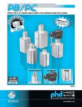
SERIES PB & PC SWING ARM CLAMPS FOR WORKHOLDING SOLUTIONS MRO Dro Replace -In! m Unit Opp ent ortunity
Abrir o catálogo na página 1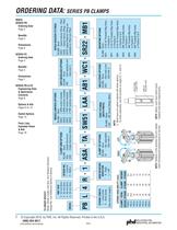
Options & Kits Pages 9 to 14 Switch Options Page 15 Parts Lists, Exploded Views & Kits Page 16 © Copyright 2010, by PHD, Inc. All Rights Reserved. Printed in the U.S.A. (800) 624-8511 CLAMP TOTAL CLAMP ROTARY SERIES STROKE STROKE STROKE CLAMP TIP OPTIONS BLANK - None TA - Std. Adjustable (See note 1) WELD COVER OPTIONS BLANK - None WC1 - Rod weld cover (See note 1) NOTE: Metric units have metric ports. Imperial units have imperial ports. ARM DOWN CLAMP PORT NOTE: 1) Must have arm option ordered with these options. To order separately, use kit numbers on pages 9, 11, and 14. NOTE: Rotation...
Abrir o catálogo na página 2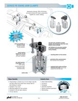
SERIES PB SWING ARM CLAMPS Application Example: PHD’s PB Clamps are used to fixture ATV frame components together for robotic welding. rod weld cover available to protect cylinder rod and bearing areas from weld splatter during clamping arms are available as finished or blank that can be tooled by the customer anti-backlash arm and guide available to minimize amount of arm backlash during clamping keyed interface between the rod and arm ensure location and easy installation mounting pattern on two surfaces controlled orifice communicationflow controls are not required two switch grooves on...
Abrir o catálogo na página 3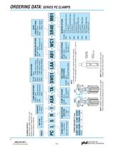
DESIGN NO. 1 - Imperial 5 - Metric CLAMP ARM OPTIONS BLANK - None ASA - Single Aluminum ASB - Single Aluminum Blank SWITCH OPTIONS - None - 1 NPN switch installed - 2 NPN switches installed - 1 PNP switch installed - 2 PNP switches installed ANTI-BACKLASH OPTIONS BLANK - None AB1 - Anti-backlash arm (See note 1) SPEED REDUCER FITTINGS BLANK -None SR40 - Speed reducer fitting - PCx5 ARM ROTATION DIRECTION R - Right L - Left CLAMP TIP OPTIONS BLANK - None TA - Std. Adjustable (See note 1) WELD COVER OPTIONS BLANK - None WC1 - Rod weld cover (See note 1) NOTE: Metric units have metric ports....
Abrir o catálogo na página 4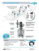
SERIES PC SWING ARM CLAMPS Application Example: PHD's PC Clamps are used to fixture and hold frame parts together in this high speed robotic welding application. angle adjustment cable routing switches mount flush protected profile Major Benefits switch ready rod weld cover available to protect cylinder rod and bearing areas from weld splatter during clamping anti-backlash arm and guide available to minimize amount of arm backlash during clamping mounting pattern on two surfaces controlled orifice communication- flow controls are not required hardened helical spline and three hardened drive...
Abrir o catálogo na página 5
DIMENSIONS: SERIES PB CLAMPS (WRENCH FLATS) 6 All dimensions are reference only unless specifically toleranced. www.phdinc.com/clamps PBCOI pilCP INDUSTRIAL AUTOMATION
Abrir o catálogo na página 6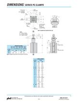
DIMENSIONS: SERIES PC CLAMPS All dimensions are reference only unless specifically toleranced. INDUSTRIAL AUTOMATION PBC01 www.phdinc.com/clamps
Abrir o catálogo na página 7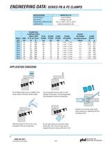
ENGINEERING DATA: SERIES PB & PC CLAMPS SPECIFICATIONS PISTON SEALS ROD SEALS OPERATING TEMPERATURE LUBRICATION SERIES PB & PC Long life Nitrile Urethane lip type -20 to +180F [-30 to +82C] Factory lubricated for life ROTARY STROKE TOLERANCE TOLERANCE including backlash mm degree - 1 mm, + 2 mm 3 - 1 mm, + 2 mm 3 - 1 mm, + 2 mm 3 - 1 mm, + 2 mm 3 - 1 mm, + 2 mm 3 - 1 mm, + 2 mm 3 - 1 mm, + 2 mm 3 - 1 mm, + 2 mm 3 - 1 mm, + 2 mm 3 APPLICATION CONCERNS LOAD Do not attach heavy arms or weights to the clamp without reducing rotation speed. Do not machine the arm while it is still attached to...
Abrir o catálogo na página 8
OPTIONS & KITS: SERIES PB & PC CLAMPS AB1 Anti-backlash arm and guide are made from hardened steel and can be used to minimize the amount of arm backlash when clamping. Maximum clearance between arm and guide is .028 in [0.71 mm] resulting in a maximum total radial play of 0.8° max. A14 HEX NOTE: 1) KIT INCLUDES: ANTI-BACKLASH ARM, GUIDE, ALL FASTENERS, AND ONE LONG MOUNTING BOLT RETAINED WITH A NUT (DISCARD NUT) 2) UNLESS OTHERWISE NOTED, ALL DIMENSIONS APPLY TO BOTH SERIES PB & PC CLAMPS EXTENDED A4 (END OF CLAMP STROKE) RETRACTED A4 (BEGINNING OF CLAMP STROKE) A16 NOTE: ARM IS EFFECTIVE...
Abrir o catálogo na página 9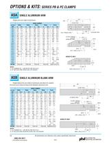
OPTIONS & KITS: SERIES PB & PC CLAMPS ASA NOTES: 1) ALL NUMBERS IN [ ] ARE METRIC AND ARE IN mm 2) KIT INCLUDES ARM, SCREW, AND LOCK WASHER 2X AS15 THREAD AS16 DP (FROM OPP SIDE) SINGLE ALUMINUM BLANK ARM NOTES: 1) ALL NUMBERS IN [ ] ARE METRIC AND ARE IN mm 2) KIT INCLUDES ARM, MOUNTING SCREW, AND LOCK WASHER 2X AB15 THREAD AB16 DP (FROM OPP SIDE) All dimensions are reference only unless specifically toleranced. www.phdinc.com/clamps
Abrir o catálogo na página 10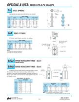
OPTIONS & KITS: SERIES PB & PC CLAMPS TA STEEL SPINDLE TA5 (ACROSS NUT FLATS) TA1 THREAD Steel spindles are plated steel with two hex nuts included. LETTER DIM TA1 TA2 TA3 TA4 TA5 TA6 KIT NO. 90° swivel metal fitting for ease of air line hook up. LETTER DIMENSION PF1 (MIN) PF2 PF3 PF4 PART NO. SELF SEALING SWIVEL MALE ELBOW FOR PF4 TUBING CLAMP PORT NOTES: 1) FITTINGS ARE ORDERED SEPARATELY 2) FITTINGS NOT AVAILABLE FOR PBx2x RELEASE PORT SPEED REDUCER FITTINGS - Size 4 SPEED REDUCER FITTINGS - Size 5 SR fittings provide a speed reducing orifice in a male to female hex connector. They...
Abrir o catálogo na página 11
OPTIONS: SERIES PB & PC CLAMPS SPEED REDUCER FITTINGS OPTION (continued) When Series PB or PC Clamps are used with standard ASA or ASB Arms, AB1 Antibacklash, WC1 Weld Covers and TA Spindles. Speed controls are NOT required. These graphs assume the following: The clamp is mounted vertically. Loads are attached to ASB Arms or identical customer-supplied aluminum arms. If longer arms or heavier loads are attached, clamps need to be protected from the higher Rotational Moment of Inertia (Jm) by slowing down their speed. PHD recommends nonadjustable speed reducing fittings for these...
Abrir o catálogo na página 12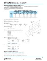
OPTIONS: SERIES PB & PC CLAMPS SPEED REDUCER FITTINGS OPTION (continued) Jm for PHD supplied options are shown in Chart A. For customer supplied arms and attached loads, use the equations below to calculate the Rotational Moment of Inertial (Jm). Stay below the maximum allowable (Jm) and apply speed reducing fittings as required. CHART A - MAXIMUM ALLOWABLE MOMENT OF INERTIA MAX. ALLOWABLE Jm in-lb-sec2 STD PORTS SR FITTINGS .009 .02 .009 .02 .03 .06 .03 .06 Jm = Rotational Mass Moment of Inertia (in-lb-sec 2) g = Gravitational Constant (386.4in/sec) weight = lb R = distance from CL of rod...
Abrir o catálogo na página 13Todos os catálogos e folhetos técnicos PHD
-
 Pneumatic Workholding Clamps
12 Páginas
-
 SERIES 5360 PROXIMITY SWITCHES
6 Páginas
-
 Series 8600
6 Páginas
-
 A, HV, AV series
64 Páginas
-
 Series GRM
96 Páginas
-
 BCK Stretching Cylinder
12 Páginas
-
 RCC series
6 Páginas
-
 GRW series
8 Páginas
-
 GRS series
10 Páginas
-
 PA series
8 Páginas
-
 Series CTS Cylinders
10 Páginas
-
 BCZ series
12 Páginas
-
 Adaptors, Transition Plates & Stanchions
46 Páginas
-
 1750 series
3 Páginas
-
 SCV series
10 Páginas
-
 1000-8000 Series
38 Páginas
-
 Multi-Motion Actuators
36 Páginas
-
 190/191 series
10 Páginas
-
 Series LC Escapements
6 Páginas
-
 Series 160 Escapements
8 Páginas
-
 CRS series
14 Páginas
-
 Clamp Image Brochure-
4 Páginas
-
 BCS series
16 Páginas
-
 Main Catalog
644 Páginas


Catálogos arquivados
-
 CLAMPS
156 Páginas