
Excertos do catálogo

Pascal molding machine system Improving the set-up time for vertical IMM
Abrir o catálogo na página 1
Clamping Clamp the workpiece Clamp the mold Clamp the tool Changing Change the workpiece Change the mold Change the tool Control Control them
Abrir o catálogo na página 2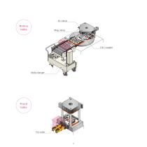
Rotary table Mold changer Fixed table
Abrir o catálogo na página 3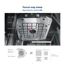
Pascal mag clamp Mag clamp for vertical IMM Upper clamp plate Magnet core Plate mount screw Displacement detection core Measures against residual magnetic flux PAT. 750kN(75ton)Vertical IMM(fixed table)Mag clamp for upper mold Magnet core Mold(big size) Mold(small size) Displacement detection core No need to unif y the mold size
Abrir o catálogo na página 4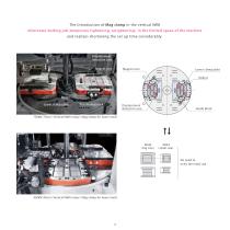
The introduction of Mag clamp in the vertical IMM eliminates bolting job(temporary tightening, retightening)in the limited space of the machine and realizes shortening the set up time considerably. Displacement detection core Magnet core Magnet core Lower clamp plate Rollers Rollers Lower clamp plate Positioning block Displacement detection core Guide block 750kN(75ton)Vertical IMM(rotary)Mag clamp for lower mold Mold Mold (big size) (small size) No need to unif y the mold size
Abrir o catálogo na página 5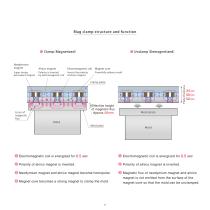
Mag clamp structure and function Neodymium magnet Alnico magnet Electromagnetic coil Magnet core Super strong permanent magnet Polarity is inverted by electromagnetic coil Inverts the polarity of alnico magnet Powerfully adheres mold Effective height of magnetic flux : Approx 20 mm Lines of magnetic flux Plate thickness Clamp plate 1 Electromagnetic coil is energized for 0 . 5 sec . 1 Electromagnetic coil is energized for 0 . 5 sec 2 Polarity of alnico magnet is inverted. 2 Polarity of alnico magnet is inverted . 3 Neodymium magnet and alnico magnet become homopolar. 3 Magnetic flux of...
Abrir o catálogo na página 6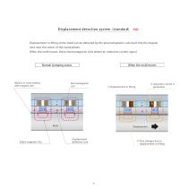
Displacement detec tion system(standard) Displacement or lifting of the mold can be detected by the electromagnetic coils built into the magnet core near the center of the clamp plates. When the mold moves, these electromagnetic coils detect an induction current signal. Normal clamping status Electromagnetic coil Stable magnetic flux ③ Induction current is generated. Mold is in close contact with magnet core When the mold moves Displacement detection core ② Flux changes due to displacement or lif
Abrir o catálogo na página 7
Mag clamp for lower mold mold loading procedure ① Loading the master mold ③-1 Table stops rotating Air clamp Mag clamp Rotary table Air clamp
Abrir o catálogo na página 8
④-1 Mold clamped by platens ⑥ Lower mold to be positioned by the procedure of ② to ⑤ ④-2 Upper Air clamp ON Mold locking ON (Clamping completion detection) (Clamping completion detection) ● The system can be securely operated with safety interlock. ● The above procedure is explained at upper mold basis. Contact Pascal for lower mol
Abrir o catálogo na página 9
Air clamp, bolted type TLA Clamp or unclamp the standardized mold by one-touch operation Screw or Unscrew the mold in the limited space is not required. Air clamp, bolted type It is the clamp with safety and high reliability, which does not lose holding force because of the strong spring and special wedge mechanism even at time of zero air pressure. 9
Abrir o catálogo na página 10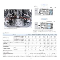
Lever Body Micro switch At time of unclamping, the lever is retracted back in the body and it does not interfere in loading/unloading the mold. Specifications Model Holding force Clamping force Residual clamping force Full stroke Clamping stroke Safety stroke Cylinder capacity Proof pressure Operating temperature ● Residual clamping force : the clamping force when air pressure drops to zero after clamp is clamped the mold at air pressur
Abrir o catálogo na página 11
Air clamp, T-slot-less slidable type TLA-M Slidable clamp for the IMM without T-slot. Air clamp, T-slot-less slidable type
Abrir o catálogo na página 12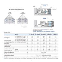
Clamp Lever No need to unify the mold size Mold (big size) Mold (small size) The clamp lever is not retracted back in the body at time of unclamping. Forward and backward of the clamp itself is manual. Specifications Model Clamping force Residual clamping force Holding force Full stroke Clamping stroke Safety stroke Standard sliding stroke Cylinder capacity Operating air pressure Proof pressure Operating temperature ● Residual clamping force : the clamping force when air pressure drops to zero after clamp is clamped the mold at air p
Abrir o catálogo na página 13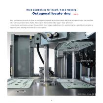
Mold positioning for insert / hoop molding Octagonal locate ring Mold positioning can easily be done by mating an octagonal locate block (mold side) to an octagonal locate ring (machine side) with visual observation sliding the mold on the machine table. (upper mold reference) Conventional positioning using a stopper block is no longer needed even the positioning by a parallel pin can also be improved. Also unifying the mold size is not required. Octagonal locate-ring
Abrir o catálogo na página 14
Platen(Mag clamp) Octagonal locate-ring Restrained 8-faces can provide easy centering. Taper allows easy mold setting Mold Octagonal locate-block High rigidity can be obtained by receiving mold weight with multiple faces. Mag clamp & Octagonal locate-ring & Rollers Octagonal locate ring & Rollers (When the ring mounted in magnet plate) (When using a automatic clamp or a manual clamp) Octagonal locate ring Octagonal locate ring Magnet plate Movable platen Movable platen Octagonal locate-block Octagonal locate-block Rollers Mold Magnet plate Rotary table Rotary table
Abrir o catálogo na página 15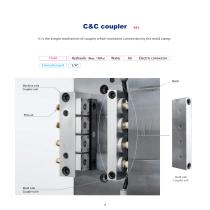
It is the simple mechanism of coupler which maintains connection by the mold clamp. Fluid Connection port Electric connector Mold Machine side Coupler unit Mold side Coupler unit Mold side Coupler unit
Abrir o catálogo na página 16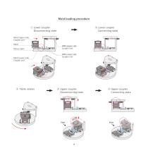
Mold loading procedure ② Lower coupler Connecting state ① Lower coupler Disconnecting state Mold(Upper)side Coupler unit Mold Rotary table Mold(Lower)side Coupler unit IMM(Upper)side Coupler unit IMM(Lower)side Coupler unit ④ Upper coupler Disconnecting state
Abrir o catálogo na página 17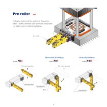
Pulling the mold out of the machine at the position where a forklift, overhead crane and mold change table can readily access to take the mold away. Removable & fold type model One-touch operation Vertically fold type model One-touch operation Mounting block Mounting block Hook
Abrir o catálogo na página 18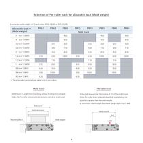
Selection of Pre-roller each for allowable load (Mold weight) In case the mold weight is 0.5 tonf, select PRA2-0630B or PRF2-0630B. Allowable load * (Mold weight) Mold travel * The allowable load of above table is for 2 pre-rollers. Mold travel Allowable load Mold travel = Length from mounting surface of block to the stopper. Static load measured at the position of 1/4 of the mold travel. Select the Pre-roller where mold dimensions are within mold travel. Select Pre-roller where allowable load (kN) multiplied by the quantity is greater than the mold weight. SI conversion : Mold weight...
Abrir o catálogo na página 19Todos os catálogos e folhetos técnicos Pascal Engineering Inc.
-
 Pascal auto coupler
60 Páginas
-
 Pascal mold change system
68 Páginas
-
 Mold clamping system
136 Páginas
-
 Press machine system
48 Páginas
-
 Stamping die clamping system
254 Páginas
-
 Pascal N2 gas springs
28 Páginas
-
 mini Gas springs
40 Páginas
-
 N2 gas springs
86 Páginas
-
 Pascal Products Introductions
76 Páginas
-
 Expansion clamp
142 Páginas
-
 air Work clamping system
130 Páginas
-
 35MPa Work clamping system
177 Páginas
-
 Pal system
106 Páginas
-
 7MPa Work clamping system
256 Páginas
-
 Pascal mag clamp
72 Páginas