
Excertos do catálogo
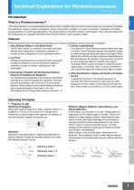
Technical Explanation for Photomicrosensors CSM_Photomicro_TG_E_4_2 Introduction Sensors A Photomicrosensor is a small photoelectronic sensor with an amplifier built into it that is used primarily as a component for building into equipment. Like any ordinary photoelectric sensor with a built-in amplifier, it is used, for example, in applications to detect passing objects or in positioning applications. The sensing object is most often a piece of metal called a "dog". When the dog enters the sensing area, it is optically detected by the Photomicrosensor, which outputs a signal. 5. Other Specifications: Degree of Protection and Output Current A waterproof structure is not required because it is assumed the Photomicrosensors will be built into other equipment, and the output current rating can be kept low. Also, most models can operate on a 5-VDC power supply. Control Components Automation Systems 3. Downsizing Is Possible with the Sensing Distances Required for Building into Equipment The standard sensing distances (slot width) are specifically intended to be used for building into equipment. Slot-type Sensors, for example, have a 3.6 mm or 5 mm sensing distance. Diffuse-reflective and Limited Reflective Sensors have a sensing distance of less than 5 mm, and Retroreflective and Through-beam Sensors, less than 1 m. Safety Components Photomicrosensors have the following advantages over ordinary photoelectric sensors with built-in amplifiers 4. Indicator Lighting Mode 1. Many Different Shapes in One Model Series The indicator on many Photomicrosensors lights when light The EE-SX67 Series, for example, has models with eight is incident. Some Photomicrosensors have specific models different slot configurations, allowing the customer to on which the indicator lights when light is interrupted. When choose the best configuration for the installation position. lighting the indicator for position adjustment applications of 2. Low Price Slot-type Sensors, for example, it may be more convenient Ratings and performances are limited to those required for to use a model that lights the indicator when light is building into equipment, and the required IP degree of interrupted. When using the indicator to check the power protection is easier to achieve, making prices very supply status, on the other hand, it may be convenient to reasonable. use a model that lights the indicator when light is incident. Operating Principles Refractive index: 1 Refractive index: 1.5 (Mirror) Regular Reflection (Mirror) Retroreflection (Paper) Others Power Supplies / In Addition Energy Conservation Support / Environment Measure Equipment Refraction Refraction is the phenomenon of light being deflected as it passes obliquely through the boundary between two media with different refractive indices. Reflection (Regular Reflection, Retroreflection, and Diffuse Reflection) A flat surface, such as glass or a mirror, reflects light at an angle equal to the incident angle of the light. This kind of reflection is called regular reflection. Retroreflectors (also called a corner cube) take advantage of this principle by arranging three flat surfaces perpendicular to each other. "Retro" means "to return toward the source." The light reflected off the reflectors travels back towards the emitter, thus the term "retroreflective". Matte surfaces, such as white paper, reflect light in all directions. This scattering of light is called diffuse reflection. This principle is the sensing method used by Diffuse-reflective Sensors. Motion / Drives 1. Properties of Light Rectilinear Propagation When light travels through air or water, it always travels in a straight line. The slit on the outside of a Through-beam Sensor that is used to detect small objects is an example of how this principle is applied to practical use. Diffuse Reflection
Abrir o catálogo na página 1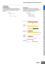
Technical Explanation for Photomicrosensors 2. Light Sources Light Generation Non-modulated Light Non-modulated light facilitates high-speed response by continuously radiating a constant amount of light. There is the drawback, however, of susceptibility to external light interference. Modulated Light Modulated light is not affected by sunlight, light from incandescent bulbs, and other external light interference. An LED emitter is pulse-lighted, and the received signal is processed to remove the DC component. Light intensity Safety Components Light intensity Light from LED Relays Light...
Abrir o catálogo na página 2
Technical Explanation for Photomicrosensors Classification 2. Considerations when Choosing a Sensing Method (1) Slot Sensors • Shape, slot width, connection (pre-wired/connector) • Presence or absence of external light interference (nonmodulated light/modulated light) • Output configuration (Light-ON/Dark-ON, NPN/PNP) • Indicator (Light-ON/Dark-ON) (2) Through-beam Sensors • Shape, sensing distance • Output configuration (Light-ON/Dark-ON) (3) Retroreflective Sensors • Sensing distance • Output configuration (Light-ON/Dark-ON) (4) Diffusive/Limited-reflective Sensors • Shape, sensing...
Abrir o catálogo na página 3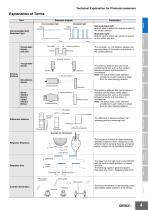
Technical Explanation for Photomicrosensors Explanation of Terms Term Reference diagram Non-modulated light Modulated light Explanation Modulated light Light intensity Light intensity Modulated light: Method used to detect light emitted in pulses by the emitter element. 0 Time Slot width Time Sensing distance The slot width, i.e., the distance between the opposing faces of the emitter and receiver, is the sensing distance. Safety Components Through-beam Sensors (with slot) Non-modulated light: Method used to detect light steadily emitted by the emitter element. Non-modulated light Sensing...
Abrir o catálogo na página 4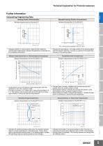
Technical Explanation for Photomicrosensors Further Information Sensing Position Characteristics Interpreting Engineering Data Repeated Sensing Position Characteristics Sample characteristics for the EE-SX77 Safety Components Parallel Movement Characteristics Sample characteristics for the EE-SPW311/411 Distance Y (mm) Control Components Receiver Output Excess Gain vs. Sensing Distance Characteristics Automation Systems Receiver output excess gain (multiple) • Indicates the discrepancy in the edge position of the sensing object when the Sensor responds. It serves as a guide for the...
Abrir o catálogo na página 5Todos os catálogos e folhetos técnicos OMRON
-
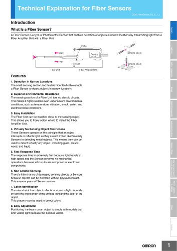 Technical Explanation for Fiber Sensors
14 Páginas
-
 D4F
D4F8 Páginas
-
 D4GS-N
11 Páginas
-
 E4E2
E4E25 Páginas
-
 Smart Laser Sensors E3NC-L/E3NC-S
16 Páginas
-
 Fiber SensorBest Selection Catalog
104 Páginas
-
 Fiber Unit E32-LT/LD
4 Páginas
-
 G9SE Series
20 Páginas
-
 NX-SL/SI/SO
20 Páginas
-
 G9SP
G9SP28 Páginas
-
 G9SX-SM
24 Páginas
-
 G9SX-SM/LM
9 Páginas
-
 G9SX/G9SX-GS
49 Páginas
-
 G9SX-LM
28 Páginas
-
 G9SB
G9SB10 Páginas
-
 G9SA
G9SA16 Páginas
-
 DST1 Series
5 Páginas
-
 WS02-CFSC1-E
3 Páginas
-
 G9SA-300-SC
9 Páginas
-
 K8AK-AS
12 Páginas
-
 K8AK-AW
16 Páginas
-
 K8AK-VS
12 Páginas
-
 K8AK-VW
12 Páginas
-
 K8AK-PH
12 Páginas
-
 K8DS-PH
12 Páginas
-
 K8AK-PM
16 Páginas
-
 K8DS-PM
12 Páginas
-
 K8AK-PA
12 Páginas
-
 K8DS-PA
12 Páginas
-
 K8AK-PW
12 Páginas
-
 K8DS-PU
12 Páginas
-
 K8DS-PZ
12 Páginas
-
 K8AK-TS/PT
12 Páginas
-
 K8AK-LS
12 Páginas
-
 K8AK-TH
12 Páginas
-
 K2CM
K2CM16 Páginas
-
 SE
SE15 Páginas
-
 SAO
SAO13 Páginas
-
 APR-S
APR-S6 Páginas
-
 XS5
XS525 Páginas
-
 XS2
XS229 Páginas
-
 F92A
F92A4 Páginas
-
 GLS
GLS3 Páginas
-
 TL-L
TL-L5 Páginas
-
 V680 series
68 Páginas
-
 V680S Series
68 Páginas
-
 MY
MY35 Páginas
-
 Safety Light Curtain F3SG-R Series
80 Páginas
-
 E3NC-L/-S
16 Páginas
-
 61F-GPN-BT / -BC
5 Páginas
-
 NE1A-SCPU Series
8 Páginas
-
![NE1A-SCPU0[]-EIP](https://img.directindustry.com/pdf/repository_di/15954/ne1a-scpu0-eip-616667_1mg.jpg) NE1A-SCPU0[]-EIP
NE1A-SCPU0[]-EIP8 Páginas
-
 NE0A-SCPU01
6 Páginas
-
 LY
LY14 Páginas
-
![G2R-[]-S](https://img.directindustry.com/pdf/repository_di/15954/g2r-s-616653_1mg.jpg) G2R-[]-S
G2R-[]-S11 Páginas
-
 G7T
G7T7 Páginas
-
 G2A
G2A9 Páginas
-
 G2A-434
7 Páginas
-
 G2AK
G2AK7 Páginas
-
 MK-S
MK-S9 Páginas
-
 MK-S(X)
12 Páginas
-
 MM
MM17 Páginas
-
 MMK
MMK14 Páginas
-
 G4Q
G4Q6 Páginas
-
 G7Z
G7Z9 Páginas
-
 G7J
G7J10 Páginas
-
 E4B
E4B12 Páginas
-
 E4A-3K
9 Páginas
-
 E4C-UDA
5 Páginas
-
 E6H-C
E6H-C5 Páginas
-
 E6F-C
E6F-C5 Páginas
-
 E6D-C
E6D-C5 Páginas
-
 E6B2-C
5 Páginas
-
 E6A2-C
5 Páginas
-
 NL
NL8 Páginas
-
 VB
VB5 Páginas
-
 SC
SC5 Páginas
-
 D5F
D5F5 Páginas
-
 D5A
D5A8 Páginas
-
 E3S-GS3E4
3 Páginas
-
 E3S-R
E3S-R11 Páginas
-
 E3S-A
E3S-A21 Páginas
-
 E3S-CL
9 Páginas
-
 E3ZM-C
14 Páginas
-
 E3T Data Sheet
26 Páginas
-
 E3T Series
6 Páginas
-
 G5 Series
59 Páginas
-
 Sysmac Catalog
410 Páginas
-
 VT-X700
6 Páginas
-
 E5AC-T
8 Páginas
-
 CP1
CP112 Páginas
-
 CP1E
CP1E12 Páginas
-
 MS4800
40 Páginas
-
 VC-DL100
6 Páginas
-
 FZ4 Series
42 Páginas
-
 ZG2
ZG216 Páginas
-
 ZS Series
32 Páginas
-
 ZW Series
24 Páginas
-
 E9NC-T
2 Páginas
-
 Vision System FH series
54 Páginas
-
 CompoNet
28 Páginas
-
 F3SJ Series Safety Light Curtain
108 Páginas
-
 Code Reader/OCR
24 Páginas
-
 Fiber Sensor Best Selection Catalog
100 Páginas
-
 Portable Multi-logger ZR-RX70
12 Páginas
-
 Air Particle Sensor ZN-PD-S
2 Páginas
-
 Smart Fiber Amplifier Units E3NX-FA
8 Páginas
-
 NT series
18 Páginas
-
 Programmable Controller SYSMAC CVM1
16 Páginas
-
 Round Water-resistant Connectors
31 Páginas
-
 Modular Temperature Controller EJ1
24 Páginas
-
 Safety Controller G9SP
28 Páginas
-
 E3FA PHOTOELECTRIC SENSORS
24 Páginas
-
 Switch Mode Power Supply S8VK-G
22 Páginas
-
 Data Logger ZR-RX Series
12 Páginas
-
 Programmable Terminals NS Series
57 Páginas
-
 DeviceNet Safety System
30 Páginas
-
 Switching Power Supplies
16 Páginas
-
 Photomicro Sensors
7 Páginas
-
 Displacement Sensors
4 Páginas
-
 R87F / R87T AC Axial Fans
28 Páginas
-
 G9SX-GS Safety Guard Switching Unit
28 Páginas
-
 H8PS Cam Positioner
32 Páginas
-
 OS32C Safety Laser Scanner
24 Páginas
-
 FQ Vision Sensor
17 Páginas
-
 UM, MC3 Safety Mat/Safety Mat Controller
19 Páginas
-
 ZN-PD Air Particle Sensor
16 Páginas
-
 ZUV-C20H / C30H Smart Curing System
14 Páginas
-
 E5CC Digital Temperature Controller
38 Páginas
-
 S8EX Switch Mode Power Supply
24 Páginas
-
 CP1L CP series CP1L CPU Unit
36 Páginas
-
 E2EF
E2EF8 Páginas
-
 FQ2 Smart camera
24 Páginas


Catálogos arquivados
-
 SAFETY APPLICATION HANDBOOK
55 Páginas
-
 SMART REMOTE I/O
12 Páginas
-
 Sensor Accessories
38 Páginas
-
 REGULATION SOLUTIONS
24 Páginas
-
 Vision Systems
20 Páginas