
Excertos do catálogo
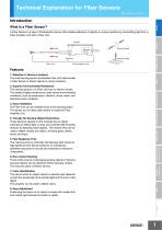
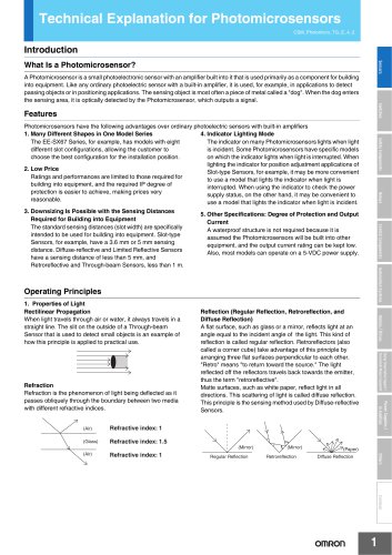
Technical Explanation for Fiber Sensors CSM_FiberSensor_TG_E_1_2 Introduction Sensors What Is a Fiber Sensor? A Fiber Sensor is a type of Photoelectric Sensor that enables detection of objects in narrow locations by transmitting light from a Fiber Amplifier Unit with a Fiber Unit. Sensing circuit Emitter Sensing object Receiver Fiber Unit Safety Components Light Sensing object Fiber Amplifier Unit 1. Detection in Narrow Locations The small sensing section and flexible Fiber Unit cable enable a Fiber Sensor to detect objects in narrow locations. Control Components 2. Superior Environmental Resistance The sensing section of a Fiber Unit has no electric circuits. This makes it highly reliable even under severe environmental conditions, such as temperature, vibration, shock, water, and electrical noise conditions. Automation Systems 3. Easy Installation The Fiber Unit can be installed close to the sensing object. This allows you to freely select where to install the Fiber Amplifier Unit. Motion / Drives 4. Virtually No Sensing Object Restrictions These Sensors operate on the principle that an object interrupts or reflects light, so they are not limited like Proximity Sensors to detecting metal objects. This means they can be used to detect virtually any object, including glass, plastic, wood, and liquid. Energy Conservation Support / Environment Measure Equipment 5. Fast Response Time The response time is extremely fast because light travels at high speed and the Sensor performs no mechanical operations because all circuits are comprised of electronic components. Power Supplies / In Addition 6. Non-contact Sensing There is little chance of damaging sensing objects or Sensors because objects can be detected without physical contact. This ensures years of Sensor service. 7. Color Identification The rate at which an object reflects or absorbs light depends on both the wavelength of the emitted light and the color of the object. This property can be used to detect colors. 8. Easy Adjustment Positioning the beam on an object is simple with models that emit visible light because the beam is visible.
Abrir o catálogo na página 1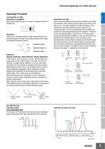
Technical Explanation for Fiber Sensors Operating Principles Safety Components Polarization of Light Light can be represented as a wave that oscillates horizontally and vertically. Fiber Sensors almost always use LEDs as the light source. The light emitted from LEDs oscillates in the vertical and horizontal directions and is referred to as unpolarized light. There are optical filters that constrain the oscillations of unpolarized light to just one direction. These are known as polarizing filters. Light from an LED that passes through a polarizing filter oscillates in only one direction and...
Abrir o catálogo na página 2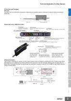
Technical Explanation for Fiber Sensors (3) Structure and Principles Structure The Fiber Unit has no electrical components whatsoever, so it provides superior resistance to noise and other environmental influences. s Fiber Unit Fiber Amplifier Unit [L/D Indicator] Indicates the setting status: Light-ON (L) or Dark-ON (D). [DPC Indicator] Turns ON when Dynamic Power Control is effective. [OUT1 Indicator/OUT2 Indicator] Turns ON when OUT1 or OUT2 is ON. Safety Components [ L/D Button] Used to switch between Light-ON (L) and Dark-ON (D). [ST Indicator] Turns ON when Smart Tuning is in...
Abrir o catálogo na página 3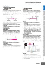
Technical Explanation for Fiber Sensors Emitter fiber - White paper - Black paper - Glass, t = 0.7 SUS304 Classification (1) Classification by Sensing Method 1. Through-beam Sensors Sensing Method The emitter and receiver fibers are installed facing each other so that the light from the emitter enters the receiver. When a sensing object passing between the emitter and receiver fibers interrupts the emitted light, it reduces the amount of light that enters the receiver. This reduction in light intensity is used to detect an object. Sensing object Receiver fiber Features • Stable operation...
Abrir o catálogo na página 4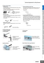
Technical Explanation for Fiber Sensors Emitter fiber Structure which has a cladding around a large number of ultrafine cores. Structure only of one fiber Receiver fiber • Coaxial Reflective Fiber Units These Fiber Units offer better detection of small objects at close distances (of 2 mm or less) than Standard Reflective Fiber Units. They also detect glossy surfaces more reliably than Standard Reflective Fiber Units, even if the surface is tilted. The receiver fibers are arranged around the emitter fiber as shown below. Safety Components • Standard Fibers This fiber have a large bending...
Abrir o catálogo na página 5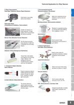
Technical Explanation for Fiber Sensors 5. Environmental Immunity Chemical-resistant, Oil-resistant 3. Beam Improvements Small-Spot, Reflective (Minute Object Detection) Made from materials that are resistant to various oils and chemicals. Small-spot to accurately detect small objects. Bending-resistant, Disconnection-resistant High-power Beam (Long-distance Installation, Dust-resistant) Safety Components Suitable for detection on large equipment, of large objects, and in environments with airborne particles Resistant to repeated bending on moving parts and breaking from snagging or shock....
Abrir o catálogo na página 6
Technical Explanation for Fiber Sensors (4) Types of Fiber Amplifier Units For information on the types of Fiber Amplifier Units and Communications Unit, refer to the product pages on your OMRON website. Switches Safety Components Relays Control Components Automation Systems Motion / Drives Energy Conservation Support / Environment Measure Equipment Power Supplies / In Addition Others Common
Abrir o catálogo na página 7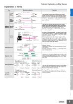
Technical Explanation for Fiber Sensors Explanation of Terms Item Explanatory diagram Meaning Sensors Sensing distance Throughbeam Sensors Emitter fiber Receiver fiber Sensing distance Retroreflective Sensors The maximum sensing distance that can be set with stability for Through-beam and Retro-reflective Sensors, taking into account product deviations and temperature fluctuations. Actual distances under standard conditions will be longer than the rated sensing distances for both types of Sensor. Emitter and receiver fibers Sensing Reflective distance Sensors Sensing object Emitter and...
Abrir o catálogo na página 8Todos os catálogos e folhetos técnicos OMRON
-
 D4F
D4F8 Páginas
-
 D4GS-N
11 Páginas
-
 E4E2
E4E25 Páginas
-
 Smart Laser Sensors E3NC-L/E3NC-S
16 Páginas
-
 Fiber SensorBest Selection Catalog
104 Páginas
-
 Fiber Unit E32-LT/LD
4 Páginas
-
 G9SE Series
20 Páginas
-
 NX-SL/SI/SO
20 Páginas
-
 G9SP
G9SP28 Páginas
-
 G9SX-SM
24 Páginas
-
 G9SX-SM/LM
9 Páginas
-
 G9SX/G9SX-GS
49 Páginas
-
 G9SX-LM
28 Páginas
-
 G9SB
G9SB10 Páginas
-
 G9SA
G9SA16 Páginas
-
 DST1 Series
5 Páginas
-
 WS02-CFSC1-E
3 Páginas
-
 G9SA-300-SC
9 Páginas
-
 K8AK-AS
12 Páginas
-
 K8AK-AW
16 Páginas
-
 K8AK-VS
12 Páginas
-
 K8AK-VW
12 Páginas
-
 K8AK-PH
12 Páginas
-
 K8DS-PH
12 Páginas
-
 K8AK-PM
16 Páginas
-
 K8DS-PM
12 Páginas
-
 K8AK-PA
12 Páginas
-
 K8DS-PA
12 Páginas
-
 K8AK-PW
12 Páginas
-
 K8DS-PU
12 Páginas
-
 K8DS-PZ
12 Páginas
-
 K8AK-TS/PT
12 Páginas
-
 K8AK-LS
12 Páginas
-
 K8AK-TH
12 Páginas
-
 K2CM
K2CM16 Páginas
-
 SE
SE15 Páginas
-
 SAO
SAO13 Páginas
-
 APR-S
APR-S6 Páginas
-
 XS5
XS525 Páginas
-
 XS2
XS229 Páginas
-
 F92A
F92A4 Páginas
-
 GLS
GLS3 Páginas
-
 TL-L
TL-L5 Páginas
-
 V680 series
68 Páginas
-
 V680S Series
68 Páginas
-
 MY
MY35 Páginas
-
 Safety Light Curtain F3SG-R Series
80 Páginas
-
 E3NC-L/-S
16 Páginas
-
 61F-GPN-BT / -BC
5 Páginas
-
 NE1A-SCPU Series
8 Páginas
-
![NE1A-SCPU0[]-EIP](https://img.directindustry.com/pdf/repository_di/15954/ne1a-scpu0-eip-616667_1mg.jpg) NE1A-SCPU0[]-EIP
NE1A-SCPU0[]-EIP8 Páginas
-
 NE0A-SCPU01
6 Páginas
-
 LY
LY14 Páginas
-
![G2R-[]-S](https://img.directindustry.com/pdf/repository_di/15954/g2r-s-616653_1mg.jpg) G2R-[]-S
G2R-[]-S11 Páginas
-
 G7T
G7T7 Páginas
-
 G2A
G2A9 Páginas
-
 G2A-434
7 Páginas
-
 G2AK
G2AK7 Páginas
-
 MK-S
MK-S9 Páginas
-
 MK-S(X)
12 Páginas
-
 MM
MM17 Páginas
-
 MMK
MMK14 Páginas
-
 G4Q
G4Q6 Páginas
-
 G7Z
G7Z9 Páginas
-
 G7J
G7J10 Páginas
-
 E4B
E4B12 Páginas
-
 E4A-3K
9 Páginas
-
 E4C-UDA
5 Páginas
-
 E6H-C
E6H-C5 Páginas
-
 E6F-C
E6F-C5 Páginas
-
 E6D-C
E6D-C5 Páginas
-
 E6B2-C
5 Páginas
-
 E6A2-C
5 Páginas
-
 NL
NL8 Páginas
-
 VB
VB5 Páginas
-
 SC
SC5 Páginas
-
 D5F
D5F5 Páginas
-
 D5A
D5A8 Páginas
-
 E3S-GS3E4
3 Páginas
-
 E3S-R
E3S-R11 Páginas
-
 E3S-A
E3S-A21 Páginas
-
 E3S-CL
9 Páginas
-
 E3ZM-C
14 Páginas
-
 E3T Data Sheet
26 Páginas
-
 E3T Series
6 Páginas
-
 G5 Series
59 Páginas
-
 Sysmac Catalog
410 Páginas
-
 VT-X700
6 Páginas
-
 E5AC-T
8 Páginas
-
 CP1
CP112 Páginas
-
 CP1E
CP1E12 Páginas
-
 MS4800
40 Páginas
-
 VC-DL100
6 Páginas
-
 FZ4 Series
42 Páginas
-
 ZG2
ZG216 Páginas
-
 ZS Series
32 Páginas
-
 ZW Series
24 Páginas
-
 E9NC-T
2 Páginas
-
 Vision System FH series
54 Páginas
-
 CompoNet
28 Páginas
-
 F3SJ Series Safety Light Curtain
108 Páginas
-
 Code Reader/OCR
24 Páginas
-
 Fiber Sensor Best Selection Catalog
100 Páginas
-
 Portable Multi-logger ZR-RX70
12 Páginas
-
 Air Particle Sensor ZN-PD-S
2 Páginas
-
 Smart Fiber Amplifier Units E3NX-FA
8 Páginas
-
 NT series
18 Páginas
-
 Programmable Controller SYSMAC CVM1
16 Páginas
-
 Round Water-resistant Connectors
31 Páginas
-
 Modular Temperature Controller EJ1
24 Páginas
-
 Safety Controller G9SP
28 Páginas
-
 E3FA PHOTOELECTRIC SENSORS
24 Páginas
-
 Switch Mode Power Supply S8VK-G
22 Páginas
-
 Data Logger ZR-RX Series
12 Páginas
-
 Programmable Terminals NS Series
57 Páginas
-
 DeviceNet Safety System
30 Páginas
-
 Switching Power Supplies
16 Páginas
-
 Photomicro Sensors
7 Páginas
-
 Displacement Sensors
4 Páginas
-
 R87F / R87T AC Axial Fans
28 Páginas
-
 G9SX-GS Safety Guard Switching Unit
28 Páginas
-
 H8PS Cam Positioner
32 Páginas
-
 OS32C Safety Laser Scanner
24 Páginas
-
 FQ Vision Sensor
17 Páginas
-
 UM, MC3 Safety Mat/Safety Mat Controller
19 Páginas
-
 ZN-PD Air Particle Sensor
16 Páginas
-
 ZUV-C20H / C30H Smart Curing System
14 Páginas
-
 E5CC Digital Temperature Controller
38 Páginas
-
 S8EX Switch Mode Power Supply
24 Páginas
-
 CP1L CP series CP1L CPU Unit
36 Páginas
-
 E2EF
E2EF8 Páginas
-
 FQ2 Smart camera
24 Páginas


Catálogos arquivados
-
 SAFETY APPLICATION HANDBOOK
55 Páginas
-
 SMART REMOTE I/O
12 Páginas
-
 Sensor Accessories
38 Páginas
-
 REGULATION SOLUTIONS
24 Páginas
-
 Vision Systems
20 Páginas