
Excertos do catálogo

Latching Relay Mechanically Latching Relays Based on the MM Power Relay • Low power consumption due to mechanical latch for economic operation. • Relays with mixed coil specifications can be produced (e.g., AC set coil and DC reset coil). • Operational response fast enough to enable pulse signal power applications. • Ambient operating temperature: –10°C to 55°C. Refer to Safety Precautions for All Relays. Ordering Information Type Contact form Open structure Solder terminals Screw terminals Plug-in (octal pins) terminals Conforming to auxiliary power DPDT+DPST-NO relay specifications Models Conforming to Auxiliary Power Relay Specifications The MM4KP-JD and MM4XKP-JD satisfy the ratings of auxiliary relays provided in JEC-2500 (1987) standards for power protective relays specified by the Japan Electromechanical Commission. Furthermore, the MM4KP-JD and MM4XKP-JD satisfy the ratings of multi-contact relays provided in JEC-174D (1979) standards for power auxiliary relays. These models work at operation level A specified by JEC-174D (1979) standards and the hot start of the relays is possible after the coils radiate heat. In accordance with JEC-2500 (1987) standards, the coil of each model withstands a 130% DC load or 115% AC load. Note: When ordering, add the rated coil voltage to the model number. Rated coil voltages are given in the coil ratings table. Example: MM2K, 6 VAC Rated coil voltage ■ Available Models Open Coils (with Solder Terminals) Type Standard Contact form Relay model Available rated voltage
Abrir o catálogo na página 1
MMK Open Coils (with Screw Terminals) Type Standard Contact form Relay model Available rated voltage Cased Coils (Plug-in Terminals) Type Standard Contact form Relay model Available rated voltage Conforming to auxiliary power relay specifications Conforming to auxiliary power relay specifications for DC-switching Model Number Legend MM@@K@ 1 1. Contact Form 2: DPDT 3: 3PDT 4: 4PDT (open structure type)/ DPDT+DPST-NO (cased type) 2. Type (see note) None: Standard X: DC-switching 3. Terminal Shape None: Solder B: Screw P: Plug-in Note: The suffix “JD” indicates models conforming to auxiliary...
Abrir o catálogo na página 2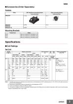
■ Accessories (Order Separately) Sockets Relay Back-connecting Socket Screw terminals Solder terminals Mounting Brackets Contact form Specifications ■ Coil Ratings Set Coil Rated voltage (V) Rated current (mA) DP Open Relays 50 Hz Open Relays Note: 1. The rated current and coil resistance are measured at a coil temperature of 23°C with tolerances of +15%/–20% for AC rated current and ±15% for DC coil resistance. 2. Performance characteristic data are measured at a coil temperature of 23°C. 3. The AC coil resistance values are reference values. 4. The maximum voltage is one that is...
Abrir o catálogo na página 3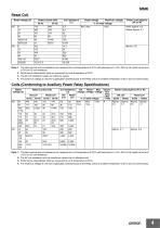
MMK Reset Coil Rated voltage (V) Maximum voltage Initial: Approx. 6.5 Rated: Approx. 4.1 Reset voltage Note: 1. The rated current and coil resistance are measured at a coil temperature of 23°C with tolerances of +15%/–20% for AC rated current and ±15% for DC coil resistance. 2. Performance characteristic data are measured at a coil temperature of 23°C. 3. The AC coil resistance values are reference values. 4. The maximum voltage is one that is applicable instantaneously to the Relay coil at an ambient temperature of 23°C and not continuously. Coils (Conforming to Auxiliary Power Relay...
Abrir o catálogo na página 4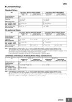
■ Contact Ratings Standard Relays Item Open Relays: MM2K(B), MM3K(B), MM4K(B) Resistive load (cosφ = 1) Resistive load (cosφ = 1) Contact mechanism Contact material Rated load Rated carry current Max. switching power (reference value) DC-switching Relays Item Open Relays: MM2XK(B), MM3XK(B), MM4XK(B) Resistive load (cosφ = 1) Contact mechanism Resistive load (cosφ = 1) Contact material Rated load Rated current flow Max. switching power (reference value) Note: 1. When switching DC inductive loads at 125 V or more, an unstable region exists for a switching current of between 0.5 and 2.5 A....
Abrir o catálogo na página 5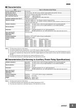
Open or bifurcated-contact Relays Contact resistance (see note 2) AC: 30 ms max.; DC: 60 ms max. (minimum pulse width for AC and DC: 100 ms) Reset time (see note 3) 30 ms max. (minimum pulse width for AC and DC: 100 ms) Mechanical: Electrical: Insulation resistance (see note 4) Dielectric strength 1,500 VAC, 50/60 Hz for 1 min between contacts of same polarity 2,000 VAC, 50/60 Hz for 1 min between contacts of different polarity, between contacts and coil, and between set and reset coils Vibration resistance Destruction: Malfunction: 10 to 55 to 10 Hz, 0.375 mm single amplitude (0.75 mm...
Abrir o catálogo na página 6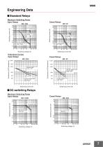
Engineering Data ■ Standard Relays Maximum Switching Power Open Relays Cased Relays AC inductive load (cosφ = 0.4) DC resistive load AC inductive load (cosφ = 0.4) Endurance Curves Open Relays Cased Relays 220 VAC resistive load Inductive load (cosφ = 0.4) 24 VDC resistive load Inductive load L/R = 7 ms MM@KP Endurance (x10 3 operations) 220 VAC resistive load Inductive load (cosφ = 0.4) 24 VDC resistive load Inductive load L/R = 7 ms ■ DC-switching Relays Maximum Switching Power Open Relays Cased Relays
Abrir o catálogo na página 7
MMK Endurance Curves Open Relays Cased Relays MM@XKP 10,000 5,000 3,000 110 VDC resistive load 1,000 500 110 VDC inductive load (L/R 7 ms) 110 VDC resistive load Inductive load L/R=7 ms ■ Relays Conforming to Auxiliary Power Relay Specifications Maximum Switching Power MMX4KP-JD AC inductive load cosφ = 0.4 AC resistive load Switching current (A) 220 VAC resistive load Inductive load cosφ = 0.4 110 VDC resistive load Inductive load L/R = 7 ms 24 VDC resistive load Inductive load L/R = 7 ms
Abrir o catálogo na página 8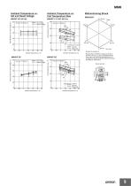
Set voltage Reset voltage Coil temperature rise (° C) Ambient Temperature vs. Coil Temperature Rise Must-operate and reset voltage (%) Ambient Temperature vs. Set and Reset Voltage Contact carry current Set coil Reset coil Number of samples: 3 Ambient temperature (°C) Set voltage Reset voltage Coil temperature rise ( ° C) Must-operate and reset voltage (%) Measurement conditions: Impose a shock of 50 m/s2 in the ±X, ±Y, and ±Z directions three times each with the Relay energized and not energized to check the shock values that cause the Relay to malfunction. Shock direction Contact carry...
Abrir o catálogo na página 9Todos os catálogos e folhetos técnicos OMRON
-
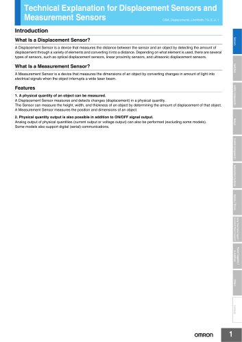
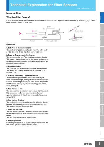 Technical Explanation for Fiber Sensors
14 Páginas
-
 D4F
D4F8 Páginas
-
 D4GS-N
11 Páginas
-
 E4E2
E4E25 Páginas
-
 Smart Laser Sensors E3NC-L/E3NC-S
16 Páginas
-
 Fiber SensorBest Selection Catalog
104 Páginas
-
 Fiber Unit E32-LT/LD
4 Páginas
-
 G9SE Series
20 Páginas
-
 NX-SL/SI/SO
20 Páginas
-
 G9SP
G9SP28 Páginas
-
 G9SX-SM
24 Páginas
-
 G9SX-SM/LM
9 Páginas
-
 G9SX/G9SX-GS
49 Páginas
-
 G9SX-LM
28 Páginas
-
 G9SB
G9SB10 Páginas
-
 G9SA
G9SA16 Páginas
-
 DST1 Series
5 Páginas
-
 WS02-CFSC1-E
3 Páginas
-
 G9SA-300-SC
9 Páginas
-
 K8AK-AS
12 Páginas
-
 K8AK-AW
16 Páginas
-
 K8AK-VS
12 Páginas
-
 K8AK-VW
12 Páginas
-
 K8AK-PH
12 Páginas
-
 K8DS-PH
12 Páginas
-
 K8AK-PM
16 Páginas
-
 K8DS-PM
12 Páginas
-
 K8AK-PA
12 Páginas
-
 K8DS-PA
12 Páginas
-
 K8AK-PW
12 Páginas
-
 K8DS-PU
12 Páginas
-
 K8DS-PZ
12 Páginas
-
 K8AK-TS/PT
12 Páginas
-
 K8AK-LS
12 Páginas
-
 K8AK-TH
12 Páginas
-
 K2CM
K2CM16 Páginas
-
 SE
SE15 Páginas
-
 SAO
SAO13 Páginas
-
 APR-S
APR-S6 Páginas
-
 XS5
XS525 Páginas
-
 XS2
XS229 Páginas
-
 F92A
F92A4 Páginas
-
 GLS
GLS3 Páginas
-
 TL-L
TL-L5 Páginas
-
 V680 series
68 Páginas
-
 V680S Series
68 Páginas
-
 MY
MY35 Páginas
-
 Safety Light Curtain F3SG-R Series
80 Páginas
-
 E3NC-L/-S
16 Páginas
-
 61F-GPN-BT / -BC
5 Páginas
-
 NE1A-SCPU Series
8 Páginas
-
![NE1A-SCPU0[]-EIP](https://img.directindustry.com/pdf/repository_di/15954/ne1a-scpu0-eip-616667_1mg.jpg) NE1A-SCPU0[]-EIP
NE1A-SCPU0[]-EIP8 Páginas
-
 NE0A-SCPU01
6 Páginas
-
 LY
LY14 Páginas
-
![G2R-[]-S](https://img.directindustry.com/pdf/repository_di/15954/g2r-s-616653_1mg.jpg) G2R-[]-S
G2R-[]-S11 Páginas
-
 G7T
G7T7 Páginas
-
 G2A
G2A9 Páginas
-
 G2A-434
7 Páginas
-
 G2AK
G2AK7 Páginas
-
 MK-S
MK-S9 Páginas
-
 MK-S(X)
12 Páginas
-
 MM
MM17 Páginas
-
 G4Q
G4Q6 Páginas
-
 G7Z
G7Z9 Páginas
-
 G7J
G7J10 Páginas
-
 E4B
E4B12 Páginas
-
 E4A-3K
9 Páginas
-
 E4C-UDA
5 Páginas
-
 E6H-C
E6H-C5 Páginas
-
 E6F-C
E6F-C5 Páginas
-
 E6D-C
E6D-C5 Páginas
-
 E6B2-C
5 Páginas
-
 E6A2-C
5 Páginas
-
 NL
NL8 Páginas
-
 VB
VB5 Páginas
-
 SC
SC5 Páginas
-
 D5F
D5F5 Páginas
-
 D5A
D5A8 Páginas
-
 E3S-GS3E4
3 Páginas
-
 E3S-R
E3S-R11 Páginas
-
 E3S-A
E3S-A21 Páginas
-
 E3S-CL
9 Páginas
-
 E3ZM-C
14 Páginas
-
 E3T Data Sheet
26 Páginas
-
 E3T Series
6 Páginas
-
 G5 Series
59 Páginas
-
 Sysmac Catalog
410 Páginas
-
 VT-X700
6 Páginas
-
 E5AC-T
8 Páginas
-
 CP1
CP112 Páginas
-
 CP1E
CP1E12 Páginas
-
 MS4800
40 Páginas
-
 VC-DL100
6 Páginas
-
 FZ4 Series
42 Páginas
-
 ZG2
ZG216 Páginas
-
 ZS Series
32 Páginas
-
 ZW Series
24 Páginas
-
 E9NC-T
2 Páginas
-
 Vision System FH series
54 Páginas
-
 CompoNet
28 Páginas
-
 F3SJ Series Safety Light Curtain
108 Páginas
-
 Code Reader/OCR
24 Páginas
-
 Fiber Sensor Best Selection Catalog
100 Páginas
-
 Portable Multi-logger ZR-RX70
12 Páginas
-
 Air Particle Sensor ZN-PD-S
2 Páginas
-
 Smart Fiber Amplifier Units E3NX-FA
8 Páginas
-
 NT series
18 Páginas
-
 Programmable Controller SYSMAC CVM1
16 Páginas
-
 Round Water-resistant Connectors
31 Páginas
-
 Modular Temperature Controller EJ1
24 Páginas
-
 Safety Controller G9SP
28 Páginas
-
 E3FA PHOTOELECTRIC SENSORS
24 Páginas
-
 Switch Mode Power Supply S8VK-G
22 Páginas
-
 Data Logger ZR-RX Series
12 Páginas
-
 Programmable Terminals NS Series
57 Páginas
-
 DeviceNet Safety System
30 Páginas
-
 Switching Power Supplies
16 Páginas
-
 Photomicro Sensors
7 Páginas
-
 Displacement Sensors
4 Páginas
-
 R87F / R87T AC Axial Fans
28 Páginas
-
 G9SX-GS Safety Guard Switching Unit
28 Páginas
-
 H8PS Cam Positioner
32 Páginas
-
 OS32C Safety Laser Scanner
24 Páginas
-
 FQ Vision Sensor
17 Páginas
-
 UM, MC3 Safety Mat/Safety Mat Controller
19 Páginas
-
 ZN-PD Air Particle Sensor
16 Páginas
-
 ZUV-C20H / C30H Smart Curing System
14 Páginas
-
 E5CC Digital Temperature Controller
38 Páginas
-
 S8EX Switch Mode Power Supply
24 Páginas
-
 CP1L CP series CP1L CPU Unit
36 Páginas
-
 E2EF
E2EF8 Páginas
-
 FQ2 Smart camera
24 Páginas


Catálogos arquivados
-
 SAFETY APPLICATION HANDBOOK
55 Páginas
-
 SMART REMOTE I/O
12 Páginas
-
 Sensor Accessories
38 Páginas
-
 REGULATION SOLUTIONS
24 Páginas
-
 Vision Systems
20 Páginas