
Excertos do catálogo

Bi-power Relays Power-switching Compact General-purpose Relays • The standard models include models that are compliant with the UL, CSA, and SEV safety standards and with the Electrical Appliances and Material Safety Act. • Equipped with an arc barrier for arc interruption. • Withstand voltages up to 2,000 V. • New built-in diode and built-in CR circuit models have joined the series. • The lineup also includes models that are compliant with the LR and VDE safety standards. • Single-pole and double-pole models have AC4 ratings and DC2 ratings (operating coil ratings: 100/ 110 VAC, 110/120 VAC, 200/220 VAC, 220/240 VAC, and 100/110 VDC). • Three-pole and four-pole models have AC4 ratings and DC2 ratings (operating coil ratings: 100/110 VAC, 200/220 VAC and 100/110 VDC). Refer to the standards certifications and compliance section of your OMRON website for the latest information on certified models. Refer to the Common Relay Precautions. Model Number Structure Relays with Plug-in Terminals Relays with PCB Terminals Case-surface mounting With operation indicators 1 Standard models Compliance with Electrical Appliances and Material Safety Act Models with diode for coil surge absorption (DC coil specification only) Models with CR circuits for coil surge absorption (AC coil specification only) Note: 1. Cells with a diagonal line cannot be manufactured. Ask your OMRON representative for details on manufacturing products for cells containing “---” in the above table. 2. If #187 tab terminals are required, use the LY1F-T2 or LY2F-T2 (single-pole or double-pole models only). 3. Refer to page 12 for information on plug-in terminal and socket combinations. 4. Items with an asterisk (*) in the table are certified for UL, CSA, and SEV. This is indicated with a certification mark on the products. 5. Items with two asterisks (**) in the table are certified for UL and CSA. This is indicated with a certification mark on the products. 6. All models in the table are certified for IEC (TÜV). 7. The models with plug-in terminals (single-pole, double-pole, and 4-pole) were combined with the PTF-E for the EC Declaration of Conformity. These products display the CE Marking.
Abrir o catálogo na página 1
Ordering Information Models with Plug-in Terminals Number of poles Classification Standard models Models with built-in operation indicators Models with single Models with built-in contacts diodes Models with built-in diodes and operation indicators Models with built-in CR circuits Models with built-in CR circuits and operation indicators Standard models 3 poles Rated voltage (V) 12, 24, 100/110, or 200/220 VAC 4 poles Rated voltage (V) 12, 24, 100/110, or 200/220 VAC Bifurcated contacts Models with built-in diodes Models with built-in diodes and operation indicators Models with built-in CR...
Abrir o catálogo na página 2
Ratings and Specifications Ratings Standard Models with Built-in Operation Indicators Operating Coil, Single-pole and Double-pole Models Item Rated voltage (V) Must-operate voltage (V) Armature ON Must-operate voltage (V) Armature ON 4 poles Item Rated voltage (V) Must-operate voltage (V) Armature ON Note: 1. The rated current and coil resistance are measured at a coil temperature of 23°C with tolerances of +15%/–20% for the AC rated current and ±15% for the DC coil resistance. 2. The AC coil resistance and inductance values are reference values only. (at 60 Hz). 3. Operating...
Abrir o catálogo na página 3
LY Refer to List of Certified Models for a list of models that are certified for safety standards and the Electrical Appliances and Material Safety Act. Classification Item Resistive load Contact type Contact materials 15 A at 110 VAC 15 A at 24 VDC Rated load Rated carry current Maximum contact voltage Maximum contact current Double-, 3-, and 4-pole models Inductive load Inductive load Resistive load (cos φ = 0.4, L/R = 7 ms) (cos φ = 0.4, L/R = 7 ms) Single Ag alloy 10 A at 110 VAC 10 A at 110 VAC 7.5 A at 110 VAC 7 A at 24 VDC 10 A at 24 VDC 5 A at 24 VDC 15 A 10 A 250 VAC 250 VAC 125...
Abrir o catálogo na página 4
Engineering Data Engineering Data Maximum Switching Capacity AC resistive load Endurance Curve AC resistive load LY2 Number of operations (×104 operations) LY1 Number of operations (×104 operations) 100 50 110 VAC inductive load (cos φ = 0.4) 24 VDC inductive load (L/R = 7 ms) 24 VDC 110 VAC inductive load inductive load (cos φ = 0.4) (L/R = 7 ms) Ambient Temperature vs. Mustoperate and Must-release Voltage LY2Z Number of operations (×104 operations) Number of operations (×104 operations) 1,000 24 VDC resistive load 110 VAC resistive load 110 VAC inductive load (cos φ = 0.4) 24 VDC...
Abrir o catálogo na página 5
Rating: 100% applied Rated power consumption: 1 W Maximum operating temperature (120° C) Rating: 100% applied Rated power consumption: 1.0 VA Maximum operating temperature (120° C) Maximum operating temperature (120° C) LY3 100/110 VAC at 50Hz Rating: 100% applied Rated power consumption: 1.6 VA Maximum operating temperature (120° C) Coil temperature rise (°C) Rating: 100% applied Rated power consumption: 1.5 W Maximum operating temperature (120° C) Coil temperature rise (°C) Coil temperature rise (°C) Rating: 100% applied Rated power consumption: 1.4 VA LY3 24 VDC Coil temperature rise...
Abrir o catálogo na página 6
N = 20 Measurement: Shock was applied 2 times each in 6 directions along 3 axes with the Relay energized and not energized to check the shock values that cause the Relay to malfunction. Criteria: Non-energized: 200 m/s2 , Energized: 200 m/s2 Shock direction Terminal Arrangement/Internal Connections (Bottom View) LY1 (Check the coil polarity when wiring and wire all connections correctly.) Note: 1. For the DC models, check the coil polarity when wiring and wire all connections correctly. 2. The indicator is red for AC and green for DC. 3. The operation indicator indicates the energization of...
Abrir o catálogo na página 7
Terminal Arrangement/Internal Connections (Bottom View) LY3-D Check the coil polarity when wiring and wire all connections correctly. Note: 1. For the DC models, check the coil polarity when wiring and wire all connections correctly. 2. The indicator is red for AC and green for DC. 3. The operation indicator indicates the energization of the coil and does not represent contact operation. Check the coil polarity when wiring and wire all connections correctly. Terminal Arrangement/Internal Connections (Bottom View) LY4 Check the coil polarity when wiring and wire all connections correctly....
Abrir o catálogo na página 8Todos os catálogos e folhetos técnicos OMRON
-
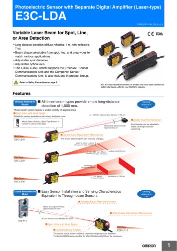
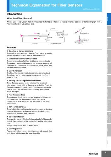 Technical Explanation for Fiber Sensors
14 Páginas
-
 D4F
D4F8 Páginas
-
 D4GS-N
11 Páginas
-
 E4E2
E4E25 Páginas
-
 Smart Laser Sensors E3NC-L/E3NC-S
16 Páginas
-
 Fiber SensorBest Selection Catalog
104 Páginas
-
 Fiber Unit E32-LT/LD
4 Páginas
-
 G9SE Series
20 Páginas
-
 NX-SL/SI/SO
20 Páginas
-
 G9SP
G9SP28 Páginas
-
 G9SX-SM
24 Páginas
-
 G9SX-SM/LM
9 Páginas
-
 G9SX/G9SX-GS
49 Páginas
-
 G9SX-LM
28 Páginas
-
 G9SB
G9SB10 Páginas
-
 G9SA
G9SA16 Páginas
-
 DST1 Series
5 Páginas
-
 WS02-CFSC1-E
3 Páginas
-
 G9SA-300-SC
9 Páginas
-
 K8AK-AS
12 Páginas
-
 K8AK-AW
16 Páginas
-
 K8AK-VS
12 Páginas
-
 K8AK-VW
12 Páginas
-
 K8AK-PH
12 Páginas
-
 K8DS-PH
12 Páginas
-
 K8AK-PM
16 Páginas
-
 K8DS-PM
12 Páginas
-
 K8AK-PA
12 Páginas
-
 K8DS-PA
12 Páginas
-
 K8AK-PW
12 Páginas
-
 K8DS-PU
12 Páginas
-
 K8DS-PZ
12 Páginas
-
 K8AK-TS/PT
12 Páginas
-
 K8AK-LS
12 Páginas
-
 K8AK-TH
12 Páginas
-
 K2CM
K2CM16 Páginas
-
 SE
SE15 Páginas
-
 SAO
SAO13 Páginas
-
 APR-S
APR-S6 Páginas
-
 XS5
XS525 Páginas
-
 XS2
XS229 Páginas
-
 F92A
F92A4 Páginas
-
 GLS
GLS3 Páginas
-
 TL-L
TL-L5 Páginas
-
 V680 series
68 Páginas
-
 V680S Series
68 Páginas
-
 MY
MY35 Páginas
-
 Safety Light Curtain F3SG-R Series
80 Páginas
-
 E3NC-L/-S
16 Páginas
-
 61F-GPN-BT / -BC
5 Páginas
-
 NE1A-SCPU Series
8 Páginas
-
![NE1A-SCPU0[]-EIP](https://img.directindustry.com/pdf/repository_di/15954/ne1a-scpu0-eip-616667_1mg.jpg) NE1A-SCPU0[]-EIP
NE1A-SCPU0[]-EIP8 Páginas
-
 NE0A-SCPU01
6 Páginas
-
![G2R-[]-S](https://img.directindustry.com/pdf/repository_di/15954/g2r-s-616653_1mg.jpg) G2R-[]-S
G2R-[]-S11 Páginas
-
 G7T
G7T7 Páginas
-
 G2A
G2A9 Páginas
-
 G2A-434
7 Páginas
-
 G2AK
G2AK7 Páginas
-
 MK-S
MK-S9 Páginas
-
 MK-S(X)
12 Páginas
-
 MM
MM17 Páginas
-
 MMK
MMK14 Páginas
-
 G4Q
G4Q6 Páginas
-
 G7Z
G7Z9 Páginas
-
 G7J
G7J10 Páginas
-
 E4B
E4B12 Páginas
-
 E4A-3K
9 Páginas
-
 E4C-UDA
5 Páginas
-
 E6H-C
E6H-C5 Páginas
-
 E6F-C
E6F-C5 Páginas
-
 E6D-C
E6D-C5 Páginas
-
 E6B2-C
5 Páginas
-
 E6A2-C
5 Páginas
-
 NL
NL8 Páginas
-
 VB
VB5 Páginas
-
 SC
SC5 Páginas
-
 D5F
D5F5 Páginas
-
 D5A
D5A8 Páginas
-
 E3S-GS3E4
3 Páginas
-
 E3S-R
E3S-R11 Páginas
-
 E3S-A
E3S-A21 Páginas
-
 E3S-CL
9 Páginas
-
 E3ZM-C
14 Páginas
-
 E3T Data Sheet
26 Páginas
-
 E3T Series
6 Páginas
-
 G5 Series
59 Páginas
-
 Sysmac Catalog
410 Páginas
-
 VT-X700
6 Páginas
-
 E5AC-T
8 Páginas
-
 CP1
CP112 Páginas
-
 CP1E
CP1E12 Páginas
-
 MS4800
40 Páginas
-
 VC-DL100
6 Páginas
-
 FZ4 Series
42 Páginas
-
 ZG2
ZG216 Páginas
-
 ZS Series
32 Páginas
-
 ZW Series
24 Páginas
-
 E9NC-T
2 Páginas
-
 Vision System FH series
54 Páginas
-
 CompoNet
28 Páginas
-
 F3SJ Series Safety Light Curtain
108 Páginas
-
 Code Reader/OCR
24 Páginas
-
 Fiber Sensor Best Selection Catalog
100 Páginas
-
 Portable Multi-logger ZR-RX70
12 Páginas
-
 Air Particle Sensor ZN-PD-S
2 Páginas
-
 Smart Fiber Amplifier Units E3NX-FA
8 Páginas
-
 NT series
18 Páginas
-
 Programmable Controller SYSMAC CVM1
16 Páginas
-
 Round Water-resistant Connectors
31 Páginas
-
 Modular Temperature Controller EJ1
24 Páginas
-
 Safety Controller G9SP
28 Páginas
-
 E3FA PHOTOELECTRIC SENSORS
24 Páginas
-
 Switch Mode Power Supply S8VK-G
22 Páginas
-
 Data Logger ZR-RX Series
12 Páginas
-
 Programmable Terminals NS Series
57 Páginas
-
 DeviceNet Safety System
30 Páginas
-
 Switching Power Supplies
16 Páginas
-
 Photomicro Sensors
7 Páginas
-
 Displacement Sensors
4 Páginas
-
 R87F / R87T AC Axial Fans
28 Páginas
-
 G9SX-GS Safety Guard Switching Unit
28 Páginas
-
 H8PS Cam Positioner
32 Páginas
-
 OS32C Safety Laser Scanner
24 Páginas
-
 FQ Vision Sensor
17 Páginas
-
 UM, MC3 Safety Mat/Safety Mat Controller
19 Páginas
-
 ZN-PD Air Particle Sensor
16 Páginas
-
 ZUV-C20H / C30H Smart Curing System
14 Páginas
-
 E5CC Digital Temperature Controller
38 Páginas
-
 S8EX Switch Mode Power Supply
24 Páginas
-
 CP1L CP series CP1L CPU Unit
36 Páginas
-
 E2EF
E2EF8 Páginas
-
 FQ2 Smart camera
24 Páginas


Catálogos arquivados
-
 SAFETY APPLICATION HANDBOOK
55 Páginas
-
 SMART REMOTE I/O
12 Páginas
-
 Sensor Accessories
38 Páginas
-
 REGULATION SOLUTIONS
24 Páginas
-
 Vision Systems
20 Páginas