
Excertos do catálogo

omRon Three-phase Voltage RelayK8AK-PW C€ cW.s @ ® Ideal for Monitoring 3-phase Power Supplies for Industrial Facilities and Equipment. • Greater resistance to inverter noise. new • Monitor overvoltages and undervoltages for three-phase 3-wire or 4-wire power supplies. DIP switch setting for 3-phase 3-wire or 3-phase 4-wire power supply. •Two SPDT output relays, 5 A at 250 VAC (resistive load). Separate outputs possible for overvoltages and undervoltages. •World-wide power specifications supported by one Unit (switchable using DIP switch). • Relay status can be monitored using LED indicator. A Refer to Safety Precautions on page 9. Refer to 8 for commonly asked questions. Ordering InformationList of Models Rated input* Note: Three-phase, three-wire or four-wire and the input range are switched using a DIP switch. * The power supply voltage is the same as the rated input voltage. •Single K8AK Monitors 3-phase Power Supply with 3 or 4 Wires Monitoring Relays can be used to monitor 3-phase power supplies with 3 or 4 wires simply by changing DIP switch settings. [Phase to phase voltage (3 wires)] | Phase to neutral voltage (4 wires)]
Abrir o catálogo na página 1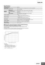
Specifications Input frequency range •Relationship of Mounting Distance between K8AK-PW Relays and Ambient Temperature (Reference Values) The following diagram shows the relationship between the mounting distances and the ambient temperature. If the relay is used with an ambient temperature that exceeds these values, the temperature of the K8AK may rise and shorten the life of the internal components. Test method Sample: K8AK-PW Mounting distances: 0, 5, and 10 mm min. DIN Track Distance between products: d
Abrir o catálogo na página 3
Connections Terminal Diagram Control Output 21 Relay output 250 VAC, 5 A (resistive load) 30 VDC, 5 A (resistive load) Input Voltages Relay Output Monitoring 3-phase, 3-wire Power Supply Note: 1. Do not connect anything to terminals that are shaded in gray. 2. Use the recommended ferrules if you use twisted wires. Power supply AC/DC Timing Charts ●Overvoltage and Undervoltage Operation Diagram Overvoltage set value Overvoltage alarm indicator Flashing Undervoltage alarm indicator Overvoltage relay 11-14 Undervoltage relay 21-24 Note: 1. K8AK-PW@ output relay is normally operative. 2. The...
Abrir o catálogo na página 4
NomenclatureFront •Indicators Item * The input across L1 and L2 is used for the internal power supply. Therefore, the power indicator will not be lit if there is no input across L1 and L2. •Setting Knobs Note: 1. Use either a solid wire of 2.5 mm2 maximum or a ferrule with insulating sleeve for the terminal connection. The length of the exposed current-carrying part inserted into the terminal must be 8 mm or less to maintain dielectric strength after connection. For 2.5 mm2 or For ferrules with smaller solid wires an insulation sleeve. Recommended ferrules Phoenix Contact • Al...
Abrir o catálogo na página 5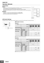
•Input Connect to L1, L2, and L3 (for three-phase three-wire mode) or L1, L2, L3, and N (for three-phase four-wire mode), depending on the mode selected using pin 2 on the DIP switch. The Unit will not operate correctly if the DIP switch setting and the wiring do not agree. Make sure the phase sequence is wired correctly. The Unit will not operate normally if the phase sequence is incorrect. •Outputs Terminals 11, 12, and 14 are the output terminals for overvoltage (SPDT). Terminals 21, 22, and 24 are the output terminals for undervoltage (SPDT). * Use the recommended ferrules if you use...
Abrir o catálogo na página 6
K8AK-PW Setting Method ●Overvoltage The overvoltage knob (OVER) is used to set the overvoltage. The overvoltage can be set to between −30% and 25% of the rated input voltage. Turn the knob while there is an input to the input terminals until the alarm indicator flashes (when the set value and the input have reached the same level.) Use this as a guide to set the voltage. The rated input depends on the model and DIP switch setting. Example: K8AK-PW1 with Pin 2 Turned OFF (Three-phase, Three-wire Mode) and Pins 3 and 4 Turned OFF (Rated Voltage of 200 V) The rated input voltage is 200 VAC and...
Abrir o catálogo na página 7
Checking Operation Overvoltage Gradually increase the input from 80% of the set value. The input value will equal the operating value when the input exceeds the set value and the alarm indicator starts flashing. Operation can be checked by the relay output that will start after the operating time has passed. Undervoltage Gradually decrease the input from 120% of the set value and check the operation using the same method as for overvoltage. Example: For monitoring mode set to three-phase three-wire monitoring, a rated voltage of 200 V, and an operating time of 5 s. Note: K8AK-PW@ output...
Abrir o catálogo na página 8
Safety Precautions Be sure to read the precautions for all models in the website at the following URL: http://www.ia.omron.com/. Warning Indications There is a risk of minor electrical shock, fire, or device failure. Do not allow any pieces of metal, conductors, or cutting chips that occur during the installation process to enter the product. Explosions may cause minor injuries. Do not use the product in locations with inflammable or explosive gases. There is a risk of minor electrical shock, fire, or device failure. Do not disassemble, modify, repair, or touch the inside of the product....
Abrir o catálogo na página 9
Precautions for Safe Use 1. Do not use or store the product in the following locations. • Locations subject to water or oil • Outdoor locations or under direct sunlight • Locations subject to dust or corrosive gases (particularly sulfurizing gases, ammonia, etc.) • Locations subject to rapid temperature changes • Locations prone to icing and dew condensation • Locations subject to excessive vibration or shock • Locations subject to wind and rain • Locations subject to static electricity and noise • Habitats of insects or small animals 2. Use and store the product in a location where the...
Abrir o catálogo na página 10
Terms and Conditions Agreement Read and understand this catalog. Please read and understand this catalog before purchasing the products. Please consult your OMRON representative if you have any questions or comments. Warranties. (a) Exclusive Warranty. Omron’s exclusive warranty is that the Products will be free from defects in materials and workmanship for a period of twelve months from the date of sale by Omron (or such other period expressed in writing by Omron). Omron disclaims all other warranties, express or implied. (b) Limitations. OMRON MAKES NO WARRANTY OR REPRESENTATION, EXPRESS...
Abrir o catálogo na página 11Todos os catálogos e folhetos técnicos OMRON
-
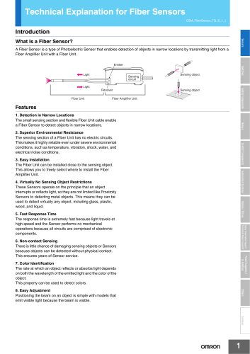 Technical Explanation for Fiber Sensors
14 Páginas
-
 D4F
D4F8 Páginas
-
 D4GS-N
11 Páginas
-
 E4E2
E4E25 Páginas
-
 Smart Laser Sensors E3NC-L/E3NC-S
16 Páginas
-
 Fiber SensorBest Selection Catalog
104 Páginas
-
 Fiber Unit E32-LT/LD
4 Páginas
-
 G9SE Series
20 Páginas
-
 NX-SL/SI/SO
20 Páginas
-
 G9SP
G9SP28 Páginas
-
 G9SX-SM
24 Páginas
-
 G9SX-SM/LM
9 Páginas
-
 G9SX/G9SX-GS
49 Páginas
-
 G9SX-LM
28 Páginas
-
 G9SB
G9SB10 Páginas
-
 G9SA
G9SA16 Páginas
-
 DST1 Series
5 Páginas
-
 WS02-CFSC1-E
3 Páginas
-
 G9SA-300-SC
9 Páginas
-
 K8AK-AS
12 Páginas
-
 K8AK-AW
16 Páginas
-
 K8AK-VS
12 Páginas
-
 K8AK-VW
12 Páginas
-
 K8AK-PH
12 Páginas
-
 K8DS-PH
12 Páginas
-
 K8AK-PM
16 Páginas
-
 K8DS-PM
12 Páginas
-
 K8AK-PA
12 Páginas
-
 K8DS-PA
12 Páginas
-
 K8DS-PU
12 Páginas
-
 K8DS-PZ
12 Páginas
-
 K8AK-TS/PT
12 Páginas
-
 K8AK-LS
12 Páginas
-
 K8AK-TH
12 Páginas
-
 K2CM
K2CM16 Páginas
-
 SE
SE15 Páginas
-
 SAO
SAO13 Páginas
-
 APR-S
APR-S6 Páginas
-
 XS5
XS525 Páginas
-
 XS2
XS229 Páginas
-
 F92A
F92A4 Páginas
-
 GLS
GLS3 Páginas
-
 TL-L
TL-L5 Páginas
-
 V680 series
68 Páginas
-
 V680S Series
68 Páginas
-
 MY
MY35 Páginas
-
 Safety Light Curtain F3SG-R Series
80 Páginas
-
 E3NC-L/-S
16 Páginas
-
 61F-GPN-BT / -BC
5 Páginas
-
 NE1A-SCPU Series
8 Páginas
-
![NE1A-SCPU0[]-EIP](https://img.directindustry.com/pdf/repository_di/15954/ne1a-scpu0-eip-616667_1mg.jpg) NE1A-SCPU0[]-EIP
NE1A-SCPU0[]-EIP8 Páginas
-
 NE0A-SCPU01
6 Páginas
-
 LY
LY14 Páginas
-
![G2R-[]-S](https://img.directindustry.com/pdf/repository_di/15954/g2r-s-616653_1mg.jpg) G2R-[]-S
G2R-[]-S11 Páginas
-
 G7T
G7T7 Páginas
-
 G2A
G2A9 Páginas
-
 G2A-434
7 Páginas
-
 G2AK
G2AK7 Páginas
-
 MK-S
MK-S9 Páginas
-
 MK-S(X)
12 Páginas
-
 MM
MM17 Páginas
-
 MMK
MMK14 Páginas
-
 G4Q
G4Q6 Páginas
-
 G7Z
G7Z9 Páginas
-
 G7J
G7J10 Páginas
-
 E4B
E4B12 Páginas
-
 E4A-3K
9 Páginas
-
 E4C-UDA
5 Páginas
-
 E6H-C
E6H-C5 Páginas
-
 E6F-C
E6F-C5 Páginas
-
 E6D-C
E6D-C5 Páginas
-
 E6B2-C
5 Páginas
-
 E6A2-C
5 Páginas
-
 NL
NL8 Páginas
-
 VB
VB5 Páginas
-
 SC
SC5 Páginas
-
 D5F
D5F5 Páginas
-
 D5A
D5A8 Páginas
-
 E3S-GS3E4
3 Páginas
-
 E3S-R
E3S-R11 Páginas
-
 E3S-A
E3S-A21 Páginas
-
 E3S-CL
9 Páginas
-
 E3ZM-C
14 Páginas
-
 E3T Data Sheet
26 Páginas
-
 E3T Series
6 Páginas
-
 G5 Series
59 Páginas
-
 Sysmac Catalog
410 Páginas
-
 VT-X700
6 Páginas
-
 E5AC-T
8 Páginas
-
 CP1
CP112 Páginas
-
 CP1E
CP1E12 Páginas
-
 MS4800
40 Páginas
-
 VC-DL100
6 Páginas
-
 FZ4 Series
42 Páginas
-
 ZG2
ZG216 Páginas
-
 ZS Series
32 Páginas
-
 ZW Series
24 Páginas
-
 E9NC-T
2 Páginas
-
 Vision System FH series
54 Páginas
-
 CompoNet
28 Páginas
-
 F3SJ Series Safety Light Curtain
108 Páginas
-
 Code Reader/OCR
24 Páginas
-
 Fiber Sensor Best Selection Catalog
100 Páginas
-
 Portable Multi-logger ZR-RX70
12 Páginas
-
 Air Particle Sensor ZN-PD-S
2 Páginas
-
 Smart Fiber Amplifier Units E3NX-FA
8 Páginas
-
 NT series
18 Páginas
-
 Programmable Controller SYSMAC CVM1
16 Páginas
-
 Round Water-resistant Connectors
31 Páginas
-
 Modular Temperature Controller EJ1
24 Páginas
-
 Safety Controller G9SP
28 Páginas
-
 E3FA PHOTOELECTRIC SENSORS
24 Páginas
-
 Switch Mode Power Supply S8VK-G
22 Páginas
-
 Data Logger ZR-RX Series
12 Páginas
-
 Programmable Terminals NS Series
57 Páginas
-
 DeviceNet Safety System
30 Páginas
-
 Switching Power Supplies
16 Páginas
-
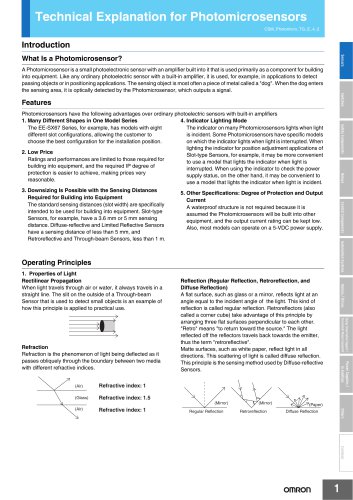
 Photomicro Sensors
7 Páginas
-
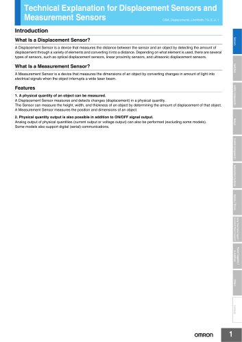
 Displacement Sensors
4 Páginas
-
 R87F / R87T AC Axial Fans
28 Páginas
-
 G9SX-GS Safety Guard Switching Unit
28 Páginas
-
 H8PS Cam Positioner
32 Páginas
-
 OS32C Safety Laser Scanner
24 Páginas
-
 FQ Vision Sensor
17 Páginas
-
 UM, MC3 Safety Mat/Safety Mat Controller
19 Páginas
-
 ZN-PD Air Particle Sensor
16 Páginas
-
 ZUV-C20H / C30H Smart Curing System
14 Páginas
-
 E5CC Digital Temperature Controller
38 Páginas
-
 S8EX Switch Mode Power Supply
24 Páginas
-
 CP1L CP series CP1L CPU Unit
36 Páginas
-
 E2EF
E2EF8 Páginas
-
 FQ2 Smart camera
24 Páginas


Catálogos arquivados
-
 SAFETY APPLICATION HANDBOOK
55 Páginas
-
 SMART REMOTE I/O
12 Páginas
-
 Sensor Accessories
38 Páginas
-
 REGULATION SOLUTIONS
24 Páginas
-
 Vision Systems
20 Páginas