
Excertos do catálogo

Low-speed Monitoring Unit Low-speed Monitoring Function Ensures Safety for Maintenance Work • Motor rotation speed detected by Proximity Sensor. • Monitors and confirms that speed does not exceed the preset level. • Includes an Enabling Switch input for maintenance work. • Detailed LED indications enable easy fault diagnosis. • PLd/Safety Category 3 (ISO 13849-1), SIL 3 (IEC/EN 62061) certified. Be sure to read the "Precautions" on page 22 Model Number Structure Model Number Legend G9SX- □□□ □ □ -□□□ - □□ 1 2 3 4 5 6 4. Output Configuration (Auxiliary output) 1: 1 output 4: 4 outputs 5. Maximum preset value Low-Speed Monitoring Unit F10: 10Hz Expansion Unit No indicator: No OFF delay 6. Terminal block type RT: Screw terminals RC: Spring-cage terminals 1. Functions LM: Low Speed Monitoring Unit EX: Expansion Unit 2. Output Configuration (Safety instantaneous output) 2: 2 outputs 4: 4 outputs 3. Output Configuration (Safety Speed detection output) 2: 2 outputs Low-speed Monitoring Unit
Abrir o catálogo na página 1
Ratings Power input
Abrir o catálogo na página 2
* The number of G9SX-EX401-D Expansion Units not included.
Abrir o catálogo na página 3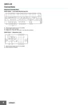
Internal ConnectionG9SX-LM224-D (Low-speed Monitoring Unit) *2 Safety output control Auxiliary output control Sensor Power supply control Expansion Unit output control *1. Internal power supply circuit is not isolated. *2. Logical AND input is isolated. *3. Outputs S14 , S24, ES1, ES2, and L1 are internally redundant. G9SX-EX401-D (Expansion Unit) *1. Internal power supply circuit is not isolated. *2. Relay outputs are isolated.
Abrir o catálogo na página 4
G9SX-LM Wiring of Inputs and Outputs Signal Name Power supply input Description of operation The input terminals for power supply. Connect the power source to the A1 and A2 terminals. Wiring Connect the power supply plus (24 VDC) to the A1 terminal. Connect the power supply minus (GND) to the A2 terminal. Using 1 safety input channel Enabling Switch To set Safety instantaneous outputs in the ON state in the Maintenance mode, HIGH state signals must be input to both of enabling input CH1 and enabling input CH2. Otherwise Safety instantaneous outputs cannot be in the ON state. Enabling Switch...
Abrir o catálogo na página 5
Connecting Safety Sensors and the G9SX-LM 1. When connecting safety sensors to the G9SX-LMD, the Y1 terminal must be connected to 24VDC for enabling input channel. Or for Safety input channel, the Y2 terminal must be connected to 24 VDC. The G9SX-LMD will detect a connection error, if the Y1 or Y2 terminal is open. 2. In many cases, safety sensor outputs include an OFF-shot pulse for self diagnosis. The following condition of test pulse is applicable as safety inputs for the G9SX. • OFF-shot pulse width of the sensor, during the ON-state: 500 ps max..
Abrir o catálogo na página 6
Operation Functions Operation Mode Relationship between G9SX-LM outputs (safety instantaneous outputs and safety speed detection outputs) and inputs (safety input, enabling input, rotation detection input) differs depends on mode selector input status. Normal operation mode (Mode selector input M1=ON, M2=OFF) Safety instantaneous outputs and safety speed detection outputs condition turn on depending on rotation detection input condition.
Abrir o catálogo na página 7
G9SX-LM Connecting Expansion Units Setting Procedure (1) Reset Mode • The G9SX-EX and G9SX-EX-T Expansion Units can be connected to the G9SX-LM@) to increase the number of safety instantaneous outputs. • When the G9SX-EX-T is connected, it will operate in the same way as G9SX-EX. • A maximum of five Expansion Units can be connected to one G9SX-LM@. This may be a combination of G9SX-EX Instantaneous types and G9SX-EX-T OFF-delayed types. • Remove the terminating connector from the receptacle on the G9SX-LM@ and insert the Expansion Unit cable connector into the receptacle. Insert the...
Abrir o catálogo na página 8
G9SX-LM (3) Setting Logical AND Connection (5) Response performance regarding speed detection When connecting two or more Units by logical AND connection, set the logical AND connection preset switch on the Unit that is on the input side to AND. The response time of the entire system regarding speed detection can be calculated by the following formula: Ts = Tp + Tf + Tr + Tm Ts Tp Tf Tr Tm Note: 1. A setting error will occur and Unit B will lock out if the logical AND setting switch on the Unit is set to OFF. 2. Set the logical AND setting switch on Unit A to OFF or the output of Unit A...
Abrir o catálogo na página 9
* Refer to Fault Detection on the next page for details.
Abrir o catálogo na página 10
Settings indication (at power ON) Settings for G9SX-LMD can be checked by indicators for approx. 3 seconds after power ON. During the settings indication term, ERR indicator will light up, however the auxiliary error output will remain OFF.
Abrir o catálogo na página 11
Note: At the following, G9SX-LMD diagnoses the proximity sensors. In that case, it is not abnormal though the operation indicator of the proximity sensor blinks. • When the rotation of the cogwheel is stopping, and both proximity sensors are turning ON.
Abrir o catálogo na página 12
If neither sensor has detected any movement for one second or longer, G9SX-LMD will detect it a: Install proximity sensors so that one of them is turned ON when the rotation of cogwheel stops. Install one proximity sensor on the center line of the concavity width, and the other on the center of the convexity width so that one of the proximity sensors will be turned ON when the rotation of the cogwheel stops. Shape of Cogwheel and Setting of Proximity Sensors 1. Installation of proximity sensors For safe and stable detection of a rotating cogwheel, install proximity sensors according to the...
Abrir o catálogo na página 13
Step 1: Calculating the number of cogwheel teeth "Input frequency range” and "Low speed detection settings” of G9SX-LM@ should be considered. According to the information above, when setting the number of cogwheel teeth at "6," the values will be as mentioned below. These values are frequencies input to rotation detection input of G9SX-LM@, falling within the ranges of "Input frequency range" and "Low speed detection settings". At normal operation (high speed): 3000 rpm x 1 / 60 x 6 = 300 Hz At low speed: 60 rpm x 1 / 60 x 6 = 6 Hz Note: When the number of rotations between cogwheel and...
Abrir o catálogo na página 14Todos os catálogos e folhetos técnicos OMRON
-
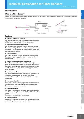 Technical Explanation for Fiber Sensors
14 Páginas
-
 D4F
D4F8 Páginas
-
 D4GS-N
11 Páginas
-
 E4E2
E4E25 Páginas
-
 Smart Laser Sensors E3NC-L/E3NC-S
16 Páginas
-
 Fiber SensorBest Selection Catalog
104 Páginas
-
 Fiber Unit E32-LT/LD
4 Páginas
-
 G9SE Series
20 Páginas
-
 NX-SL/SI/SO
20 Páginas
-
 G9SP
G9SP28 Páginas
-
 G9SX-SM
24 Páginas
-
 G9SX-SM/LM
9 Páginas
-
 G9SX/G9SX-GS
49 Páginas
-
 G9SB
G9SB10 Páginas
-
 G9SA
G9SA16 Páginas
-
 DST1 Series
5 Páginas
-
 WS02-CFSC1-E
3 Páginas
-
 G9SA-300-SC
9 Páginas
-
 K8AK-AS
12 Páginas
-
 K8AK-AW
16 Páginas
-
 K8AK-VS
12 Páginas
-
 K8AK-VW
12 Páginas
-
 K8AK-PH
12 Páginas
-
 K8DS-PH
12 Páginas
-
 K8AK-PM
16 Páginas
-
 K8DS-PM
12 Páginas
-
 K8AK-PA
12 Páginas
-
 K8DS-PA
12 Páginas
-
 K8AK-PW
12 Páginas
-
 K8DS-PU
12 Páginas
-
 K8DS-PZ
12 Páginas
-
 K8AK-TS/PT
12 Páginas
-
 K8AK-LS
12 Páginas
-
 K8AK-TH
12 Páginas
-
 K2CM
K2CM16 Páginas
-
 SE
SE15 Páginas
-
 SAO
SAO13 Páginas
-
 APR-S
APR-S6 Páginas
-
 XS5
XS525 Páginas
-
 XS2
XS229 Páginas
-
 F92A
F92A4 Páginas
-
 GLS
GLS3 Páginas
-
 TL-L
TL-L5 Páginas
-
 V680 series
68 Páginas
-
 V680S Series
68 Páginas
-
 MY
MY35 Páginas
-
 Safety Light Curtain F3SG-R Series
80 Páginas
-
 E3NC-L/-S
16 Páginas
-
 61F-GPN-BT / -BC
5 Páginas
-
 NE1A-SCPU Series
8 Páginas
-
![NE1A-SCPU0[]-EIP](https://img.directindustry.com/pdf/repository_di/15954/ne1a-scpu0-eip-616667_1mg.jpg) NE1A-SCPU0[]-EIP
NE1A-SCPU0[]-EIP8 Páginas
-
 NE0A-SCPU01
6 Páginas
-
 LY
LY14 Páginas
-
![G2R-[]-S](https://img.directindustry.com/pdf/repository_di/15954/g2r-s-616653_1mg.jpg) G2R-[]-S
G2R-[]-S11 Páginas
-
 G7T
G7T7 Páginas
-
 G2A
G2A9 Páginas
-
 G2A-434
7 Páginas
-
 G2AK
G2AK7 Páginas
-
 MK-S
MK-S9 Páginas
-
 MK-S(X)
12 Páginas
-
 MM
MM17 Páginas
-
 MMK
MMK14 Páginas
-
 G4Q
G4Q6 Páginas
-
 G7Z
G7Z9 Páginas
-
 G7J
G7J10 Páginas
-
 E4B
E4B12 Páginas
-
 E4A-3K
9 Páginas
-
 E4C-UDA
5 Páginas
-
 E6H-C
E6H-C5 Páginas
-
 E6F-C
E6F-C5 Páginas
-
 E6D-C
E6D-C5 Páginas
-
 E6B2-C
5 Páginas
-
 E6A2-C
5 Páginas
-
 NL
NL8 Páginas
-
 VB
VB5 Páginas
-
 SC
SC5 Páginas
-
 D5F
D5F5 Páginas
-
 D5A
D5A8 Páginas
-
 E3S-GS3E4
3 Páginas
-
 E3S-R
E3S-R11 Páginas
-
 E3S-A
E3S-A21 Páginas
-
 E3S-CL
9 Páginas
-
 E3ZM-C
14 Páginas
-
 E3T Data Sheet
26 Páginas
-
 E3T Series
6 Páginas
-
 G5 Series
59 Páginas
-
 Sysmac Catalog
410 Páginas
-
 VT-X700
6 Páginas
-
 E5AC-T
8 Páginas
-
 CP1
CP112 Páginas
-
 CP1E
CP1E12 Páginas
-
 MS4800
40 Páginas
-
 VC-DL100
6 Páginas
-
 FZ4 Series
42 Páginas
-
 ZG2
ZG216 Páginas
-
 ZS Series
32 Páginas
-
 ZW Series
24 Páginas
-
 E9NC-T
2 Páginas
-
 Vision System FH series
54 Páginas
-
 CompoNet
28 Páginas
-
 F3SJ Series Safety Light Curtain
108 Páginas
-
 Code Reader/OCR
24 Páginas
-
 Fiber Sensor Best Selection Catalog
100 Páginas
-
 Portable Multi-logger ZR-RX70
12 Páginas
-
 Air Particle Sensor ZN-PD-S
2 Páginas
-
 Smart Fiber Amplifier Units E3NX-FA
8 Páginas
-
 NT series
18 Páginas
-
 Programmable Controller SYSMAC CVM1
16 Páginas
-
 Round Water-resistant Connectors
31 Páginas
-
 Modular Temperature Controller EJ1
24 Páginas
-
 Safety Controller G9SP
28 Páginas
-
 E3FA PHOTOELECTRIC SENSORS
24 Páginas
-
 Switch Mode Power Supply S8VK-G
22 Páginas
-
 Data Logger ZR-RX Series
12 Páginas
-
 Programmable Terminals NS Series
57 Páginas
-
 DeviceNet Safety System
30 Páginas
-
 Switching Power Supplies
16 Páginas
-
 Photomicro Sensors
7 Páginas
-
 Displacement Sensors
4 Páginas
-
 R87F / R87T AC Axial Fans
28 Páginas
-
 G9SX-GS Safety Guard Switching Unit
28 Páginas
-
 H8PS Cam Positioner
32 Páginas
-
 OS32C Safety Laser Scanner
24 Páginas
-
 FQ Vision Sensor
17 Páginas
-
 UM, MC3 Safety Mat/Safety Mat Controller
19 Páginas
-
 ZN-PD Air Particle Sensor
16 Páginas
-
 ZUV-C20H / C30H Smart Curing System
14 Páginas
-
 E5CC Digital Temperature Controller
38 Páginas
-
 S8EX Switch Mode Power Supply
24 Páginas
-
 CP1L CP series CP1L CPU Unit
36 Páginas
-
 E2EF
E2EF8 Páginas
-
 FQ2 Smart camera
24 Páginas


Catálogos arquivados
-
 SAFETY APPLICATION HANDBOOK
55 Páginas
-
 SMART REMOTE I/O
12 Páginas
-
 Sensor Accessories
38 Páginas
-
 REGULATION SOLUTIONS
24 Páginas
-
 Vision Systems
20 Páginas