
Excertos do catálogo

For the most recent information on models that have been certified for safety standards, refer to your OMRON website. The G9SA Series Offers a Complete Line-up of Compact Units. • Four kinds of 45-mm wide Units are available: A 3-pole model, a 5-pole model, and models with 3 poles and 2 OFF-delay poles, as well as a Two-hand Controller. Also available are 17.5-mm wide Expansion Units with 3 poles and 3 OFF-delay poles. • Simple expansion connection. • OFF-delay models have 15-step OFF-delay settings. • Conforms to EN ISO13849-1 (PLe/Safety Category 4) *. • Both DIN track mounting and screw mounting are possible. * Except for some models. Refer to "Applicable Performance Level (PL)" on page 13, or "Reliability data for safety of control components_SISTEMA library" on OMRON's website. A Be sure to read the “Safety Precautions”on page 15 Model Number Structure Model Number Legend Note: 1. Please see “Ordering Information” on page 2 for the actual models that can be ordered. 2. Specify the power supply voltage when ordering. 1. Function None: Emergency stop EX: Expansion Unit 5. Input Configuration None: 1-channel or 2-channel input possible 6. OFF-delay Time (Max. setting time) None: No OFF-delay T075: 7.5 seconds T1 5: 15 seconds
Abrir o catálogo na página 1
| Specify the power supply voltage when ordering. Emergency-stop Units Note: Set to maximum values in the factory.
Abrir o catálogo na página 2
Power Input Item Model * When an Expansion Unit is connected, the power consumption is increased by 2 VA/2 W max. Inputs Item Model * When an Expansion Unit is connected, the input current is increased by 30 mA max. Contacts *1. The contact resistance was measured with 1 A at 5 VDC using the voltage-drop method. *2. Not Including bounce time. *3. The response time is the time it takes for the main contact to open after the input is turned OFF. Includes bounce time. *4. The insulation resistance was measured with 500 VDC at the same places that the dielectric strength was checked. *5....
Abrir o catálogo na página 3
Control circuit Control circuit Control circuit Control circuit Control circuit Control circuit Control circuit Control circuit Note: 1. With 100 to 240-VAC type, be sure to connect PE to a protective ground. With 24-VAC/VDC type, if the power supply is not connected to a protective ground, be sure to connect PE to a protective ground. 2. With 24-VAC/VDC type, the power supply terminals A1 and A2 have polarities. A2 is the negative pole. *1. Use terminals A and B to switch reset mode. A to B open: Manual reset A to B closed: Auto-reset *2. Terminal T23 is used for 2-channel input with a...
Abrir o catálogo na página 4
*1. Terminal T23 Terminal T23 is used for 2-channel input with a positive common (when connecting a safety sensor with a PNP output). When T23 is being used, please open T21 and T22. For 1-channel input, short circuit T12-T23 before use. *2. Output Contacts G9SA-301: Safety Output Contacts 13-14, 23-24, 33-34. Auxiliary Contact 41-42. G9SA-501: Safety Output Contacts 13-14, 23-24, 33-34, 43-44, 53-54. Auxiliary Contact 61-62. G9SA-321-TQ Safety Output Contacts 13-14, 23-24, 33-34. Safety OFF-delay Output Contact 43-44, 53-54. Auxiliary Contact 61-62. *3. Terminals A and B A-B Opening:...
Abrir o catálogo na página 5
Dimensions and Terminal Arrangement Twenty, M3 Twenty-four, M3 Twenty-four, M3 Twenty-one, M3 Connector cover * Note 1: The OFF-delay time setting switch is found on the G9SA-321-T@ only. 2: The K1 to K4 indicators light when the NO contacts of internal relays K1 to K4 close. * Do not remove unless an Expansion Unit is being used. PWR (green) K1 (green) K2 (green) OFF-delay time setting switch (See note 1) Note 1: The OFF-delay time setting switch is found on the G9SA-EX031-T@ only. 2: The K1 and K2 indicators light when the NO contacts of internal relays K1 and K2 close. OFF-delay time...
Abrir o catálogo na página 6
Application ExamplesG9SA-301 (24 VAC/VDC) with 2-channel Limit Switch Input/Auto-reset Highest achievable PL/ safety category Note: The above PL is only the evaluation result of the example. The PL must be evaluated in an actual application by the customer after confirming the usage conditions. •Application Overview • The power supply to the motor M is turned OFF when the S1 and S2 detect that the guard is opened. • The power supply to the motor M is kept OFF until the guard is closed. Timing Chart Limit switches S1 and S2 _ S1: Safety limit switch KM1 and KM2: Magnetic contactor...
Abrir o catálogo na página 7
G9SA-301 (24 VAC/VDC) with 2-channel Limit Switch Input/Manual Reset Highest achievable PL/ safety category Note: The above PL is only the evaluation result of the example. The PL must be evaluated in an actual application by the customer after confirming the usage conditions. •Application Overview • The power supply to the motor M is turned OFF when the S1 and S2 detect that the guard is opened. • The power supply to the motor M is kept OFF until the guard is closed and the reset switch S3 is pressed. Safety limit switch Limit switch Reset switch Magnetic contactor Motor
Abrir o catálogo na página 8
G9SA-301 (100 to 240 VAC) with 2-channel Limit Switch Input/Auto-reset Highest achievable PL/ safety category Note: The above PL is only the evaluation result of the example. The PL must be evaluated in an actual application by the customer after confirming the usage conditions. •Application Overview • The power supply to the motor M is turned OFF when the S1 and S2 detect that the guard is opened. • The power supply to the motor M is kept OFF until the guard is closed. Safety limit switch Limit switch Magnetic contactor Motor
Abrir o catálogo na página 9
G9SA-301 (24 VAC/VDC) with 2-channel Emergency Stop Switch Input/Manual Reset Highest achievable PL/ safety category Note: The above PL is only the evaluation result of the example. The PL must be evaluated in an actual application by the customer after confirming the usage conditions. •Application Overview • The power supply to the motor M is turned OFF when the emergency stop switch is pressed. • The power supply to the motor M is kept OFF until the reset switch S2 is pressed while the emergency stop switch is released. Timing Chart Emergency stop switch S1 Reset switch S2 KM1 and...
Abrir o catálogo na página 10Todos os catálogos e folhetos técnicos OMRON
-
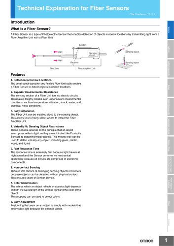 Technical Explanation for Fiber Sensors
14 Páginas
-
 D4F
D4F8 Páginas
-
 D4GS-N
11 Páginas
-
 E4E2
E4E25 Páginas
-
 Smart Laser Sensors E3NC-L/E3NC-S
16 Páginas
-
 Fiber SensorBest Selection Catalog
104 Páginas
-
 Fiber Unit E32-LT/LD
4 Páginas
-
 G9SE Series
20 Páginas
-
 NX-SL/SI/SO
20 Páginas
-
 G9SP
G9SP28 Páginas
-
 G9SX-SM
24 Páginas
-
 G9SX-SM/LM
9 Páginas
-
 G9SX/G9SX-GS
49 Páginas
-
 G9SX-LM
28 Páginas
-
 G9SB
G9SB10 Páginas
-
 DST1 Series
5 Páginas
-
 WS02-CFSC1-E
3 Páginas
-
 G9SA-300-SC
9 Páginas
-
 K8AK-AS
12 Páginas
-
 K8AK-AW
16 Páginas
-
 K8AK-VS
12 Páginas
-
 K8AK-VW
12 Páginas
-
 K8AK-PH
12 Páginas
-
 K8DS-PH
12 Páginas
-
 K8AK-PM
16 Páginas
-
 K8DS-PM
12 Páginas
-
 K8AK-PA
12 Páginas
-
 K8DS-PA
12 Páginas
-
 K8AK-PW
12 Páginas
-
 K8DS-PU
12 Páginas
-
 K8DS-PZ
12 Páginas
-
 K8AK-TS/PT
12 Páginas
-
 K8AK-LS
12 Páginas
-
 K8AK-TH
12 Páginas
-
 K2CM
K2CM16 Páginas
-
 SE
SE15 Páginas
-
 SAO
SAO13 Páginas
-
 APR-S
APR-S6 Páginas
-
 XS5
XS525 Páginas
-
 XS2
XS229 Páginas
-
 F92A
F92A4 Páginas
-
 GLS
GLS3 Páginas
-
 TL-L
TL-L5 Páginas
-
 V680 series
68 Páginas
-
 V680S Series
68 Páginas
-
 MY
MY35 Páginas
-
 Safety Light Curtain F3SG-R Series
80 Páginas
-
 E3NC-L/-S
16 Páginas
-
 61F-GPN-BT / -BC
5 Páginas
-
 NE1A-SCPU Series
8 Páginas
-
![NE1A-SCPU0[]-EIP](https://img.directindustry.com/pdf/repository_di/15954/ne1a-scpu0-eip-616667_1mg.jpg) NE1A-SCPU0[]-EIP
NE1A-SCPU0[]-EIP8 Páginas
-
 NE0A-SCPU01
6 Páginas
-
 LY
LY14 Páginas
-
![G2R-[]-S](https://img.directindustry.com/pdf/repository_di/15954/g2r-s-616653_1mg.jpg) G2R-[]-S
G2R-[]-S11 Páginas
-
 G7T
G7T7 Páginas
-
 G2A
G2A9 Páginas
-
 G2A-434
7 Páginas
-
 G2AK
G2AK7 Páginas
-
 MK-S
MK-S9 Páginas
-
 MK-S(X)
12 Páginas
-
 MM
MM17 Páginas
-
 MMK
MMK14 Páginas
-
 G4Q
G4Q6 Páginas
-
 G7Z
G7Z9 Páginas
-
 G7J
G7J10 Páginas
-
 E4B
E4B12 Páginas
-
 E4A-3K
9 Páginas
-
 E4C-UDA
5 Páginas
-
 E6H-C
E6H-C5 Páginas
-
 E6F-C
E6F-C5 Páginas
-
 E6D-C
E6D-C5 Páginas
-
 E6B2-C
5 Páginas
-
 E6A2-C
5 Páginas
-
 NL
NL8 Páginas
-
 VB
VB5 Páginas
-
 SC
SC5 Páginas
-
 D5F
D5F5 Páginas
-
 D5A
D5A8 Páginas
-
 E3S-GS3E4
3 Páginas
-
 E3S-R
E3S-R11 Páginas
-
 E3S-A
E3S-A21 Páginas
-
 E3S-CL
9 Páginas
-
 E3ZM-C
14 Páginas
-
 E3T Data Sheet
26 Páginas
-
 E3T Series
6 Páginas
-
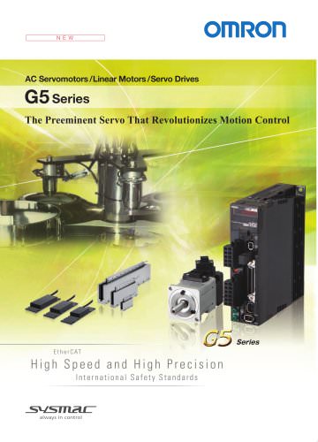
 G5 Series
59 Páginas
-
 Sysmac Catalog
410 Páginas
-
 VT-X700
6 Páginas
-
 E5AC-T
8 Páginas
-
 CP1
CP112 Páginas
-
 CP1E
CP1E12 Páginas
-
 MS4800
40 Páginas
-
 VC-DL100
6 Páginas
-
 FZ4 Series
42 Páginas
-
 ZG2
ZG216 Páginas
-
 ZS Series
32 Páginas
-
 ZW Series
24 Páginas
-
 E9NC-T
2 Páginas
-
 Vision System FH series
54 Páginas
-
 CompoNet
28 Páginas
-
 F3SJ Series Safety Light Curtain
108 Páginas
-
 Code Reader/OCR
24 Páginas
-
 Fiber Sensor Best Selection Catalog
100 Páginas
-
 Portable Multi-logger ZR-RX70
12 Páginas
-
 Air Particle Sensor ZN-PD-S
2 Páginas
-
 Smart Fiber Amplifier Units E3NX-FA
8 Páginas
-
 NT series
18 Páginas
-
 Programmable Controller SYSMAC CVM1
16 Páginas
-
 Round Water-resistant Connectors
31 Páginas
-
 Modular Temperature Controller EJ1
24 Páginas
-
 Safety Controller G9SP
28 Páginas
-
 E3FA PHOTOELECTRIC SENSORS
24 Páginas
-
 Switch Mode Power Supply S8VK-G
22 Páginas
-
 Data Logger ZR-RX Series
12 Páginas
-
 Programmable Terminals NS Series
57 Páginas
-
 DeviceNet Safety System
30 Páginas
-
 Switching Power Supplies
16 Páginas
-
 Photomicro Sensors
7 Páginas
-
 Displacement Sensors
4 Páginas
-
 R87F / R87T AC Axial Fans
28 Páginas
-
 G9SX-GS Safety Guard Switching Unit
28 Páginas
-
 H8PS Cam Positioner
32 Páginas
-
 OS32C Safety Laser Scanner
24 Páginas
-
 FQ Vision Sensor
17 Páginas
-
 UM, MC3 Safety Mat/Safety Mat Controller
19 Páginas
-
 ZN-PD Air Particle Sensor
16 Páginas
-
 ZUV-C20H / C30H Smart Curing System
14 Páginas
-
 E5CC Digital Temperature Controller
38 Páginas
-
 S8EX Switch Mode Power Supply
24 Páginas
-
 CP1L CP series CP1L CPU Unit
36 Páginas
-
 E2EF
E2EF8 Páginas
-
 FQ2 Smart camera
24 Páginas


Catálogos arquivados
-
 SAFETY APPLICATION HANDBOOK
55 Páginas
-
 SMART REMOTE I/O
12 Páginas
-
 Sensor Accessories
38 Páginas
-
 REGULATION SOLUTIONS
24 Páginas
-
 Vision Systems
20 Páginas