![G2R-[]-S](#https://img.directindustry.com/pdf/repository_di/15954/g2r-s-616653_1b.jpg)
Excertos do catálogo
![G2R-[]-S - 1](https://img.directindustry.com/pdf/repository_di/15954/g2r-s-616653_1m.jpg)
General-purpose Relay Slim and Space-saving Power Plug-in Relay ■ Lockable test button models now available. ■ Built-in mechanical operation indicator. ■ Provided with nameplate. ■ AC type is equipped with a coil-disconnection self-diagnostic function (LED type). ■ High switching power (1-pole: 10 A). ■ Environment-friendly (Cd, Pb free). ■ Wide range of Sockets also available. For the most recent information on models that have been certified for safety standards, refer to your OMRON website. Model Number Structure Model Number Legend G2R 2. Number of Poles 1: 1 pole 2: 2 poles 6. Classification Blank: General-purpose N: LED indicator D: Diode ND: LED indicator and diode NI: LED indicator with test button NDI: LED indicator and diode with test button 3. Contact Form Blank: SPDT 4. Contact Type Blank: Single 7. Rated Coil Voltage Ordering Information List of Models Classification Enclosure rating Coil ratings Plug-in terminal Diode LED indicator and diode LED indicator and diode with test button LED indicator LED indicator with test button Contact form SPDT Note: 1. The standard models are compliant with UL/CSA and VDE standards. Also, an EC compliance declaration has been made for combinations with the P2RF-E and P2RF-S. The Relays bear the CE Marking. 2. Refer to Connecting Sockets, below, for applicable Socket models. 3. When ordering, add the rated coil voltage and "(S)" to the model number. Rated coil voltages are given in the coil ratings table. New model Example: G2R-1-S 12 VDC (S) Rated coil voltage
Abrir o catálogo na página 1![G2R-[]-S - 2](https://img.directindustry.com/pdf/repository_di/15954/g2r-s-616653_2m.jpg)
G2R-@-S Accessories (Order Separately) Connecting Sockets Track/surface-mounting Socket Applicable Relay model Screwless clamp terminal Screw terminal Back-mounting Socket Solder terminals Solder terminals Note: Use of the P2CM Clip & Release Lever is recommended to ensure stable mounting. Accessories for Screwless Clamp Terminal Socket (Option) Name Clip & Release Lever Socket Bridge Mounting Tracks Applicable Socket Mounting track Track-connecting Socket Spacer Mounting plate Back-connecting Socket * Used to mount several P2R-05A and P2R-08A Connecting Sockets side by side. Specifications...
Abrir o catálogo na página 2![G2R-[]-S - 3](https://img.directindustry.com/pdf/repository_di/15954/g2r-s-616653_3m.jpg)
G2R-@-S Contact Ratings Number of poles Resistive load (cosφ = 1) Inductive load (cosφ = 0.4; L/R = 7 ms) Resistive load (cosφ = 1) 2 poles Inductive load (cosφ = 0.4; L/R = 7 ms) Rated load Rated carry current Failure rate (reference value) Characteristics Item Contact resistance Release (reset) time Mechanical: Electrical: Insulation resistance Dielectric strength 5,000 VAC, 50/60 Hz for 1 min between coil and 5,000 VAC, 50/60 Hz for 1 min between coil and contacts*; contacts*; 3,000 VAC, 50/60 Hz for 1 min between contacts of different polarity 1,000 VAC, 50/60 Hz for 1 min between...
Abrir o catálogo na página 3![G2R-[]-S - 4](https://img.directindustry.com/pdf/repository_di/15954/g2r-s-616653_4m.jpg)
Engineering Data Maximum Switching Power Plug-in Relays G2R-2-S AC inductive load (cosφ = 0.4) 10 DC resistive load DC inductive load (L/R = 7 ms) AC inductive load (cosφ = 0.4) Endurance Plug-in Relays G2R-2-S 10,000 250-VAC inductive load (cosφ = 0.4) 30-VDC inductive load (L/R = 7ms) 250-VAC/30-VDC resistive load 250-VAC 50 inductive load (cosφ = 0.4) Maximum voltage (%) Ambient Temperature vs Maximum Coil Voltage Note: The maximum voltage refers to the maximum value in a varying range of operating power voltage, not a continuous voltage. Ambient temperature (°C)
Abrir o catálogo na página 4![G2R-[]-S - 5](https://img.directindustry.com/pdf/repository_di/15954/g2r-s-616653_5m.jpg)
Dimensions Note: All units are in millimeters unless otherwise indicated. Relays with Plug-in Terminals SPDT Relays G2R-1-S, G2R-1-SN, G2R-1-SNI (S) G2R-1-SD, G2R-1-SND, G2R-1-SNDI (S) Terminal Arrangement/Internal Connections (Bottom View) G2R-1-SD (DC) Terminal Arrangement/Internal Connections (Bottom View) G2R-2-S
Abrir o catálogo na página 5![G2R-[]-S - 6](https://img.directindustry.com/pdf/repository_di/15954/g2r-s-616653_6m.jpg)
G2R-@-S Track/Surface Mounting Sockets 38.2 max. Terminal Arrangement (Top View) Option (with ejector and label attached) Standard model Terminal Arrangement (Top View) Standard model Option (with ejector and label attached) Accessories for P2RF-@-S Socket Bridge Clip and Release Lever Insulating coating
Abrir o catálogo na página 6![G2R-[]-S - 7](https://img.directindustry.com/pdf/repository_di/15954/g2r-s-616653_7m.jpg)
Terminal Arrangement (Top View) Mounting Holes (for Surface Mounting) 3.2-dia. hole Note: Pin numbers in parentheses apply to DIN standard. Terminal Arrangement (Top View) Mounting Holes (for Surface Mounting) Terminal Arrangement (Top View) Mounting Holes (for Surface Mounting) 4.2-dia. hole Terminal Arrangement (Top View) Mounting Holes (for Surface Mounting) 4.2-dia. hole
Abrir o catálogo na página 7![G2R-[]-S - 8](https://img.directindustry.com/pdf/repository_di/15954/g2r-s-616653_8m.jpg)
G2R-@-S Mounting Height of Relay with Track/Surface Mounting Sockets P2RF-@-E Terminal Arrangement (Bottom View) Mounting Holes Tolerance: ±0.1 4 Terminal Arrangement (Bottom View) 7.5 Terminal plate thickness: 0.3
Abrir o catálogo na página 8![G2R-[]-S - 9](https://img.directindustry.com/pdf/repository_di/15954/g2r-s-616653_9m.jpg)
Terminal Arrangement (Bottom View) Panel Cutout Five, 3 x 1.8-dia. holes 13.6±0.1 6 Terminal plate thickness: 0.3 Recommended thickness of the panel is 1.6 to 2.0 mm 7.5 Terminal plate thickness: 0.3 Terminal Arrangement (Bottom View) Terminal Arrangement (Bottom View) Mounting Height of Relay with Back-connecting Sockets G2R-@P
Abrir o catálogo na página 9![G2R-[]-S - 10](https://img.directindustry.com/pdf/repository_di/15954/g2r-s-616653_10m.jpg)
It is recommended to use a panel 1.6 to 2.0 mm thick. Precautions Cation • Do not use the test button for any purpose other than testing. Be sure not to touch the test button accidentally as this will turn the contacts ON. Before using the test button, confirm that circuits, the load, and any other connected item will operate safely. • Check that the test button is released before turning ON relay circuits. • If the test button is pulled out too forcefully, it may bypass the momentary testing position and go straight into the locked position. • Use an insulated tool when you operate the...
Abrir o catálogo na página 10![G2R-[]-S - 11](https://img.directindustry.com/pdf/repository_di/15954/g2r-s-616653_11m.jpg)
Read and Understand This Catalog Please read and understand this catalog before purchasing the products. Please consult your OMRON representative if you have any questions or comments. Warranty and Limitations of Liability WARRANTY OMRON's exclusive warranty is that the products are free from defects in materials and workmanship for a period of one year (or other period if specified) from date of sale by OMRON. OMRON MAKES NO WARRANTY OR REPRESENTATION, EXPRESS OR IMPLIED, REGARDING NON-INFRINGEMENT, MERCHANTABILITY, OR FITNESS FOR PARTICULAR PURPOSE OF THE PRODUCTS. ANY BUYER OR USER...
Abrir o catálogo na página 11Todos os catálogos e folhetos técnicos OMRON
-
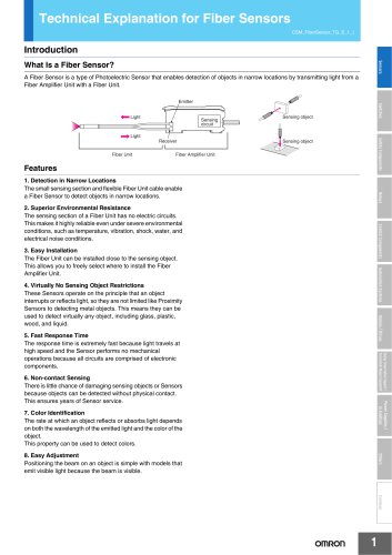 Technical Explanation for Fiber Sensors
14 Páginas
-
 D4F
D4F8 Páginas
-
 D4GS-N
11 Páginas
-
 E4E2
E4E25 Páginas
-
 Smart Laser Sensors E3NC-L/E3NC-S
16 Páginas
-
 Fiber SensorBest Selection Catalog
104 Páginas
-
 Fiber Unit E32-LT/LD
4 Páginas
-
 G9SE Series
20 Páginas
-
 NX-SL/SI/SO
20 Páginas
-
 G9SP
G9SP28 Páginas
-
 G9SX-SM
24 Páginas
-
 G9SX-SM/LM
9 Páginas
-
 G9SX/G9SX-GS
49 Páginas
-
 G9SX-LM
28 Páginas
-
 G9SB
G9SB10 Páginas
-
 G9SA
G9SA16 Páginas
-
 DST1 Series
5 Páginas
-
 WS02-CFSC1-E
3 Páginas
-
 G9SA-300-SC
9 Páginas
-
 K8AK-AS
12 Páginas
-
 K8AK-AW
16 Páginas
-
 K8AK-VS
12 Páginas
-
 K8AK-VW
12 Páginas
-
 K8AK-PH
12 Páginas
-
 K8DS-PH
12 Páginas
-
 K8AK-PM
16 Páginas
-
 K8DS-PM
12 Páginas
-
 K8AK-PA
12 Páginas
-
 K8DS-PA
12 Páginas
-
 K8AK-PW
12 Páginas
-
 K8DS-PU
12 Páginas
-
 K8DS-PZ
12 Páginas
-
 K8AK-TS/PT
12 Páginas
-
 K8AK-LS
12 Páginas
-
 K8AK-TH
12 Páginas
-
 K2CM
K2CM16 Páginas
-
 SE
SE15 Páginas
-
 SAO
SAO13 Páginas
-
 APR-S
APR-S6 Páginas
-
 XS5
XS525 Páginas
-
 XS2
XS229 Páginas
-
 F92A
F92A4 Páginas
-
 GLS
GLS3 Páginas
-
 TL-L
TL-L5 Páginas
-
 V680 series
68 Páginas
-
 V680S Series
68 Páginas
-
 MY
MY35 Páginas
-
 Safety Light Curtain F3SG-R Series
80 Páginas
-
 E3NC-L/-S
16 Páginas
-
 61F-GPN-BT / -BC
5 Páginas
-
 NE1A-SCPU Series
8 Páginas
-
![NE1A-SCPU0[]-EIP](https://img.directindustry.com/pdf/repository_di/15954/ne1a-scpu0-eip-616667_1mg.jpg) NE1A-SCPU0[]-EIP
NE1A-SCPU0[]-EIP8 Páginas
-
 NE0A-SCPU01
6 Páginas
-
 LY
LY14 Páginas
-
 G7T
G7T7 Páginas
-
 G2A
G2A9 Páginas
-
 G2A-434
7 Páginas
-
 G2AK
G2AK7 Páginas
-
 MK-S
MK-S9 Páginas
-
 MK-S(X)
12 Páginas
-
 MM
MM17 Páginas
-
 MMK
MMK14 Páginas
-
 G4Q
G4Q6 Páginas
-
 G7Z
G7Z9 Páginas
-
 G7J
G7J10 Páginas
-
 E4B
E4B12 Páginas
-
 E4A-3K
9 Páginas
-
 E4C-UDA
5 Páginas
-
 E6H-C
E6H-C5 Páginas
-
 E6F-C
E6F-C5 Páginas
-
 E6D-C
E6D-C5 Páginas
-
 E6B2-C
5 Páginas
-
 E6A2-C
5 Páginas
-
 NL
NL8 Páginas
-
 VB
VB5 Páginas
-
 SC
SC5 Páginas
-
 D5F
D5F5 Páginas
-
 D5A
D5A8 Páginas
-
 E3S-GS3E4
3 Páginas
-
 E3S-R
E3S-R11 Páginas
-
 E3S-A
E3S-A21 Páginas
-
 E3S-CL
9 Páginas
-
 E3ZM-C
14 Páginas
-
 E3T Data Sheet
26 Páginas
-
 E3T Series
6 Páginas
-
 G5 Series
59 Páginas
-
 Sysmac Catalog
410 Páginas
-
 VT-X700
6 Páginas
-
 E5AC-T
8 Páginas
-
 CP1
CP112 Páginas
-
 CP1E
CP1E12 Páginas
-
 MS4800
40 Páginas
-
 VC-DL100
6 Páginas
-
 FZ4 Series
42 Páginas
-
 ZG2
ZG216 Páginas
-
 ZS Series
32 Páginas
-
 ZW Series
24 Páginas
-
 E9NC-T
2 Páginas
-
 Vision System FH series
54 Páginas
-
 CompoNet
28 Páginas
-
 F3SJ Series Safety Light Curtain
108 Páginas
-
 Code Reader/OCR
24 Páginas
-
 Fiber Sensor Best Selection Catalog
100 Páginas
-
 Portable Multi-logger ZR-RX70
12 Páginas
-
 Air Particle Sensor ZN-PD-S
2 Páginas
-
 Smart Fiber Amplifier Units E3NX-FA
8 Páginas
-
 NT series
18 Páginas
-
 Programmable Controller SYSMAC CVM1
16 Páginas
-
 Round Water-resistant Connectors
31 Páginas
-
 Modular Temperature Controller EJ1
24 Páginas
-
 Safety Controller G9SP
28 Páginas
-
 E3FA PHOTOELECTRIC SENSORS
24 Páginas
-
 Switch Mode Power Supply S8VK-G
22 Páginas
-
 Data Logger ZR-RX Series
12 Páginas
-
 Programmable Terminals NS Series
57 Páginas
-
 DeviceNet Safety System
30 Páginas
-
 Switching Power Supplies
16 Páginas
-
 Photomicro Sensors
7 Páginas
-
 Displacement Sensors
4 Páginas
-
 R87F / R87T AC Axial Fans
28 Páginas
-
 G9SX-GS Safety Guard Switching Unit
28 Páginas
-
 H8PS Cam Positioner
32 Páginas
-
 OS32C Safety Laser Scanner
24 Páginas
-
 FQ Vision Sensor
17 Páginas
-
 UM, MC3 Safety Mat/Safety Mat Controller
19 Páginas
-
 ZN-PD Air Particle Sensor
16 Páginas
-
 ZUV-C20H / C30H Smart Curing System
14 Páginas
-
 E5CC Digital Temperature Controller
38 Páginas
-
 S8EX Switch Mode Power Supply
24 Páginas
-
 CP1L CP series CP1L CPU Unit
36 Páginas
-
 E2EF
E2EF8 Páginas
-
 FQ2 Smart camera
24 Páginas


Catálogos arquivados
-
 SAFETY APPLICATION HANDBOOK
55 Páginas
-
 SMART REMOTE I/O
12 Páginas
-
 Sensor Accessories
38 Páginas
-
 REGULATION SOLUTIONS
24 Páginas
-
 Vision Systems
20 Páginas