
Excertos do catálogo
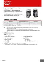
Power Relay Highly Reliable, 4-pole Miniature Relay Ideal for Sequence Control • Card lift-off employed for greater life and stable quality. • Long endurance and stable quality are assured by card lift-off system. • Mounting interchangeability with MY-series Relays. • Operation indicator mechanism incorporated for at-a-glance monitoring of ON/OFF operation. In addition, a built-in operation indicator model is also included in this Relay Series. Ordering Information Classification Plug-in terminals/Solder terminals Standard model Arc barrier equipped model Built-in diode model Built-in operation indicator model Built-in operation indicator and diode model Note: 1. When placing your order, add the coil voltage rating listed in the specifications to the model number as shown below. Example: G2A-432A 100/110 VAC Rated coil voltage 2. Built-in diode model and the operating coil of the G2A-432A-N1 are available only with DC ratings. 3. The Latching Relay (G2AK) and Fully sealed Relay (G2A-434A) developed based on the G2A are also available in this series. Model Number Legend G2A-@@@@@-@ 1 1. Number of Poles and Contact Form 4: 4PDT 2. Contact Type 3: Crossbar bifurcated 3. Enclosure Construction 2: Casing 4. Terminal Shape A: Plug-in 1P: PCB 5. Safety Breaking Mechanism None: No Y: Arc barrier 6. Special Element None: Standard D: Built-in diode N: Built-in operation indicator N1: Built-in operation indicator and diode Note: 1. The coil of the G2A-432A-N1 or a built-in diode model operates with DC only. 2. The G2A Series include the G2A-434A Power Relay and G2AK Latching Relay. Refer to G2A-434 and G2AK for details.
Abrir o catálogo na página 1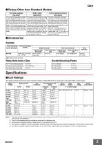
G2A ■ Relays Other than Standard Models Arc barrier equipped Built-in diode Built-in operation indicator G2A-432A-N The arc barrier equipped model is a relay designed to prevent arc short-circuiting between phases and can be used in a circuit which has potential difference between phases. The switching power of such a circuit with potential difference must be limited to less than 1/2 the rated load when using this Relay. The built-in diode model is a relay which incorporates a diode for absorption of the reverse voltage that may be generated when the coil is de-energized. Because the...
Abrir o catálogo na página 2
G2A ■ Contact Ratings Load Resistive load (cosφ = 1) Contact type Contact material Movable: Fixed: Rated load Rated carry current Inductive load (cosφ = 0.4) (L/R = 7 ms) Crossbar bifurcated AgAu-clad AgPd AgPd 0.2 A at 110 VAC 0.3 A at 24 VDC Standard/Acr barrier equipped/Built-in operation Built-in diode/Built-in operation indicator models indicator models (G2A-@-N) (G2A-@-N1) Contact resistance (see note 2) Operate time (see note 3) Release time (see note 3) Mechanical: 18,000 operations/hour Electrical: 1,800 operations/hour (under rated load) Insulation resistance (see note 4)...
Abrir o catálogo na página 3
Engineering Data Endurance Endurance (x103 operations) Maximum Switching Power AC resistive load AC inductive load (cosφ = 0.4) 10,000 5,000 24-VDC resistive load 24-VDC inductive load L/R = 7 ms 110-VAC inductive load cosφ = 0.4 Ambient Temperature vs. Coil Temperature Rise Must-operate voltage Must-release voltage Coil temperature rise ( ° C) Must-operate and reset voltage (%) Ambient Temperature vs. Must-operate and Must-release Voltage Contact carry current Shock direction Must-operate and reset voltage (%) Must-operate voltage Must-release voltage Contact carry current Coil temperature...
Abrir o catálogo na página 4
G2A Contact Reliability (Improved Allen-Bradley Test Circuit) Contact Reliability (JIS C 4530 Allen-Bradley Test Circuit) Carry contact Break contact Make contact Self-holding contact Carry contact Break contact Make contact Self-holding contact Coil Self-load Life Curve Carry contact Break contact Make contact Self-holding contact Contact load: 1 mA at 5 VDC (resistive load) Failure criterion contact resistance: 100 Ω Relay Mounting Adjacent Distance vs. Coil Temperature Rise Condition: The saturated coil temperature is measured with rated coil voltage (24 VDC) imposed. Relay mounting...
Abrir o catálogo na página 5
Accessories (Order Separately) Connecting Sockets Front-connecting Socket Back-connecting Socket Solder terminals Wire-wrap terminals PY14-Y2 (with Relay Hold-down Clip) PY14QN(2)-Y2 (with Relay Hold-down Clip) Note: 1. The PYF@A-TU is a high-humidity relay with nickel-plated rustproof terminal screws that are the same as the PYF@A in size. 2. The PYF14T is slightly different from the PYF14A(-TU) in shape and size. 3. The PYF@A-E is a finger-protection model, for which round terminals are not available. Use fork-shaped terminals or equivalent ones instead. PY14-3 Back-connecting Socket...
Abrir o catálogo na página 6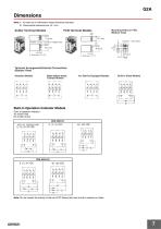
Dimensions Note: 1. All units are in millimeters unless otherwise indicated. 2. Dimensional tolerances are ±0.1 mm. Solder Terminal Models Mounting Holes on PCB (Bottom View) Fourteen, 1.2-dia. 1.2 holes x 3 elliptic holes Terminal Arrangement/Internal Connections (Bottom View) Standard Models Make-before-break Contact Models Arc Barrier Equipped Models Built-in Diode Models Built-in Operation Indicator Models Color of operation indicator AC model: Red DC model: Green G2A-432A-N Note: Do not reverse the polarity of the coil of DC Relays that have a built-in indicator or diode.
Abrir o catálogo na página 7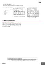
G2A Socket Mounting Plates (t = 1.6 mm) Use any of these plates when mounting two or more Sockets side-by-side PYP-1 (for Single Socket Mounting) PYP-18 and PYP-36 can be cut to a desired length for mounting less than 18 or 36 Sockets, respectively. 13.1 27.4 x 17 = 465.8±0.6 Safety Precautions Refer to Safety Precautions for All Relays. A DC coil model with a built-in indicator or built-in diode has coil polarity. Be sure to wire the terminals correctly, otherwise the diode may be broken or the operating indicator may not be lit. Furthermore, as a result of the short-circuiting of the...
Abrir o catálogo na página 8
Read and Understand This Catalog Please read and understand this catalog before purchasing the products. Please consult your OMRON representative if you have any questions or comments. Warranty and Limitations of Liability WARRANTY OMRON's exclusive warranty is that the products are free from defects in materials and workmanship for a period of one year (or other period if specified) from date of sale by OMRON. OMRON MAKES NO WARRANTY OR REPRESENTATION, EXPRESS OR IMPLIED, REGARDING NON-INFRINGEMENT, MERCHANTABILITY, OR FITNESS FOR PARTICULAR PURPOSE OF THE PRODUCTS. ANY BUYER OR USER...
Abrir o catálogo na página 9Todos os catálogos e folhetos técnicos OMRON
-
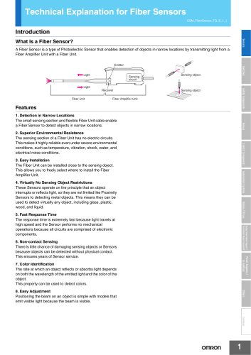 Technical Explanation for Fiber Sensors
14 Páginas
-
 D4F
D4F8 Páginas
-
 D4GS-N
11 Páginas
-
 E4E2
E4E25 Páginas
-
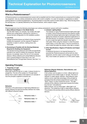
 Smart Laser Sensors E3NC-L/E3NC-S
16 Páginas
-
 Fiber SensorBest Selection Catalog
104 Páginas
-
 Fiber Unit E32-LT/LD
4 Páginas
-
 G9SE Series
20 Páginas
-
 NX-SL/SI/SO
20 Páginas
-
 G9SP
G9SP28 Páginas
-
 G9SX-SM
24 Páginas
-
 G9SX-SM/LM
9 Páginas
-
 G9SX/G9SX-GS
49 Páginas
-
 G9SX-LM
28 Páginas
-
 G9SB
G9SB10 Páginas
-
 G9SA
G9SA16 Páginas
-
 DST1 Series
5 Páginas
-
 WS02-CFSC1-E
3 Páginas
-
 G9SA-300-SC
9 Páginas
-
 K8AK-AS
12 Páginas
-
 K8AK-AW
16 Páginas
-
 K8AK-VS
12 Páginas
-
 K8AK-VW
12 Páginas
-
 K8AK-PH
12 Páginas
-
 K8DS-PH
12 Páginas
-
 K8AK-PM
16 Páginas
-
 K8DS-PM
12 Páginas
-
 K8AK-PA
12 Páginas
-
 K8DS-PA
12 Páginas
-
 K8AK-PW
12 Páginas
-
 K8DS-PU
12 Páginas
-
 K8DS-PZ
12 Páginas
-
 K8AK-TS/PT
12 Páginas
-
 K8AK-LS
12 Páginas
-
 K8AK-TH
12 Páginas
-
 K2CM
K2CM16 Páginas
-
 SE
SE15 Páginas
-
 SAO
SAO13 Páginas
-
 APR-S
APR-S6 Páginas
-
 XS5
XS525 Páginas
-
 XS2
XS229 Páginas
-
 F92A
F92A4 Páginas
-
 GLS
GLS3 Páginas
-
 TL-L
TL-L5 Páginas
-
 V680 series
68 Páginas
-
 V680S Series
68 Páginas
-
 MY
MY35 Páginas
-
 Safety Light Curtain F3SG-R Series
80 Páginas
-
 E3NC-L/-S
16 Páginas
-
 61F-GPN-BT / -BC
5 Páginas
-
 NE1A-SCPU Series
8 Páginas
-
![NE1A-SCPU0[]-EIP](https://img.directindustry.com/pdf/repository_di/15954/ne1a-scpu0-eip-616667_1mg.jpg) NE1A-SCPU0[]-EIP
NE1A-SCPU0[]-EIP8 Páginas
-
 NE0A-SCPU01
6 Páginas
-
 LY
LY14 Páginas
-
![G2R-[]-S](https://img.directindustry.com/pdf/repository_di/15954/g2r-s-616653_1mg.jpg) G2R-[]-S
G2R-[]-S11 Páginas
-
 G7T
G7T7 Páginas
-
 G2A-434
7 Páginas
-
 G2AK
G2AK7 Páginas
-
 MK-S
MK-S9 Páginas
-
 MK-S(X)
12 Páginas
-
 MM
MM17 Páginas
-
 MMK
MMK14 Páginas
-
 G4Q
G4Q6 Páginas
-
 G7Z
G7Z9 Páginas
-
 G7J
G7J10 Páginas
-
 E4B
E4B12 Páginas
-
 E4A-3K
9 Páginas
-
 E4C-UDA
5 Páginas
-
 E6H-C
E6H-C5 Páginas
-
 E6F-C
E6F-C5 Páginas
-
 E6D-C
E6D-C5 Páginas
-
 E6B2-C
5 Páginas
-
 E6A2-C
5 Páginas
-
 NL
NL8 Páginas
-
 VB
VB5 Páginas
-
 SC
SC5 Páginas
-
 D5F
D5F5 Páginas
-
 D5A
D5A8 Páginas
-
 E3S-GS3E4
3 Páginas
-
 E3S-R
E3S-R11 Páginas
-
 E3S-A
E3S-A21 Páginas
-
 E3S-CL
9 Páginas
-
 E3ZM-C
14 Páginas
-
 E3T Data Sheet
26 Páginas
-
 E3T Series
6 Páginas
-
 G5 Series
59 Páginas
-
 Sysmac Catalog
410 Páginas
-
 VT-X700
6 Páginas
-
 E5AC-T
8 Páginas
-
 CP1
CP112 Páginas
-
 CP1E
CP1E12 Páginas
-
 MS4800
40 Páginas
-
 VC-DL100
6 Páginas
-
 FZ4 Series
42 Páginas
-
 ZG2
ZG216 Páginas
-
 ZS Series
32 Páginas
-
 ZW Series
24 Páginas
-
 E9NC-T
2 Páginas
-
 Vision System FH series
54 Páginas
-
 CompoNet
28 Páginas
-
 F3SJ Series Safety Light Curtain
108 Páginas
-
 Code Reader/OCR
24 Páginas
-
 Fiber Sensor Best Selection Catalog
100 Páginas
-
 Portable Multi-logger ZR-RX70
12 Páginas
-
 Air Particle Sensor ZN-PD-S
2 Páginas
-
 Smart Fiber Amplifier Units E3NX-FA
8 Páginas
-
 NT series
18 Páginas
-
 Programmable Controller SYSMAC CVM1
16 Páginas
-
 Round Water-resistant Connectors
31 Páginas
-
 Modular Temperature Controller EJ1
24 Páginas
-
 Safety Controller G9SP
28 Páginas
-
 E3FA PHOTOELECTRIC SENSORS
24 Páginas
-
 Switch Mode Power Supply S8VK-G
22 Páginas
-
 Data Logger ZR-RX Series
12 Páginas
-
 Programmable Terminals NS Series
57 Páginas
-
 DeviceNet Safety System
30 Páginas
-
 Switching Power Supplies
16 Páginas
-
 Photomicro Sensors
7 Páginas
-
 Displacement Sensors
4 Páginas
-
 R87F / R87T AC Axial Fans
28 Páginas
-
 G9SX-GS Safety Guard Switching Unit
28 Páginas
-
 H8PS Cam Positioner
32 Páginas
-
 OS32C Safety Laser Scanner
24 Páginas
-
 FQ Vision Sensor
17 Páginas
-
 UM, MC3 Safety Mat/Safety Mat Controller
19 Páginas
-
 ZN-PD Air Particle Sensor
16 Páginas
-
 ZUV-C20H / C30H Smart Curing System
14 Páginas
-
 E5CC Digital Temperature Controller
38 Páginas
-
 S8EX Switch Mode Power Supply
24 Páginas
-
 CP1L CP series CP1L CPU Unit
36 Páginas
-
 E2EF
E2EF8 Páginas
-
 FQ2 Smart camera
24 Páginas


Catálogos arquivados
-
 SAFETY APPLICATION HANDBOOK
55 Páginas
-
 SMART REMOTE I/O
12 Páginas
-
 Sensor Accessories
38 Páginas
-
 REGULATION SOLUTIONS
24 Páginas
-
 Vision Systems
20 Páginas