
Excertos do catálogo
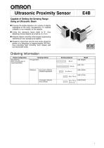
Ultrasonic Proximity Sensor Capable of Setting the Sensing Range Using an Ultrasonic Beam Ensures the stable detection of a variety of objects regardless of the color, transparency, or material (metallic or non-metallic) of the objects. Limits the ultrasonic beam width to 8°, thus detecting minute objects as small as 2 x 2 cm. Detects objects smoothly while largely suppressing interference from background objects. Sealed to resist dust and dirt and emits ultrasonic waves at a frequency of approximately 200 kHz, thus providing high immunity from impact and environmental noise. Ordering Information Output configuration DC switching NPN (normally open or closed selectable) Sensing method Sensing distance Convergent reflective (Distance adjustable) Convergent reflective (Zone setting) Sensing zone
Abrir o catálogo na página 1
E4B Sensing Method Detects the attenuation or interrupted condition of the ultrasonic beam caused by the object E4B-TjS Emitter passing between the Emitter and Receiver. Convergent reflective distance Detects only the beam reflected from the object existing within the sensing distance range set with the distance adjuster. Sensing object E4B-TjR Receiver Unstable range Convergent reflective zone Sensing object passing zone Detects the object with the interruption of the normal beam reflected from the reflector. Sensing object passing zone Sensing distance adjustable range Sensing object...
Abrir o catálogo na página 2
Specifications Ratings/Characteristics Model Sensing method Sensing distance Convergent reflective zone 20 to 60 cm (20 to 70 cm) (see note 1) (in 10-cm divisions) Item 12 to 24 VDC ± 10% (10.8 to 26.4 VDC) with a max. ripple ±10% (p-p) Supply voltage Current consumption Convergent reflective distance Standard sensing object Differential travel Directional angle (see note 2) Ultrasonic oscillation frequency Response frequency (see note 4) Operating mode Incident or interrupted (selectable) Control output NPN, 100 mA at 30 VDC (with a residual voltage of 1.5 V max.) and an output resistance...
Abrir o catálogo na página 3
Engineering Data E4B-TS50E4: Sensitivity adjuster set to Max. Sensitivity adjuster: Adjust with stable incident. Sensitivity adjuster: Adjust with stable incident. Sensing position X (cm) (from Receiver) Note: Sample: Round pipe that is 10 cm long min. The curve with the sensitivity adjuster Note: set to maximum indicates the size of the sensing object. Standard sensing object (40 x 40 flat plate) E4B-LS70E4, E4B-RS70E4 Sample: Round pipe that is 10 cm long min. The sensing method will change when the sensing distance exceeds 10 cm. As a result, the detectable diameters will change greatly....
Abrir o catálogo na página 4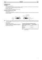
1. STABILITY Indicator (Green) When this indicator is lit, the ultrasonic input into the Receiver is sufficient, or its interruption is small enough, to ensure the smooth operation of the E4B. Do not operate the E4B when this indicator is not lit. 2. SENSING Indicator (Red) When this indicator is lit, the Receiver has ultrasonic input. Indicator of Through-beam Emitter 1. Incident Indicator Lit when there is ultrasonic input. To use this indicator of the Emitter as an SENSING indicator like the indicator on the Receiver, connect the black lead wires of the Emitter and Receiver together....
Abrir o catálogo na página 5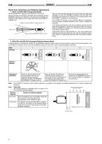
E4B Beam Axis, Sensitivity, and Distance Adjustments 1. E4B-T1 and E4B-TS50 Through-beam Models Set the SENSITIVITY adjuster of the Receiver to maximum. Move the Emitter and Receiver vertically and horizontally until the SENSING indicator of the Receiver is lit and secure the Emitter and Receiver at the midpoint of the range within which the STABILITY indicator is lit. Range in which the STABILITY indicator (green) is lit Optimum line Range in which the SENSING indicator (red) is lit Pass the sensing object through the sensing range and adjust the sensitivity so that the SENSING indicator...
Abrir o catálogo na página 6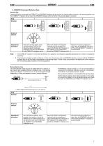
E4B 3. E4B-RS70 Convergent Reflective Zone General Use Locate the Sensor so that both the STABILITY and SENSING indicators will be lit when the sensing object is placed at the sensing position and the STABILITY indicator will be lit and the SENSING indicator will be off when the sensing object is removed. Step Distance selector Adjustment procedure Sensing object Sensing object Sensing object Move the Emitter and Receiver vertically and horizontally and secure the Emitter and Receiver at the midpoint of the range within which the STABILITY indicator is lit. Place the sensing object at the...
Abrir o catálogo na página 7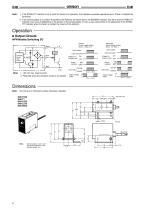
1. If the STABILITY indicator is not lit while the Sensor is in operation, this indicates a possible operational error. Check or readjust the sensitivity. 2. If the sensing object is in position A parallel to the Reflector as shown above, the SENSING indicator may be lit and the STABILITY indicator may not be lit depending on the position of the sensing object. In such a case, give priority to the adjustment of the STABILITY indicator when the beam is incident by means of the reflector. Operation Output Circuits NPN Models Switching DC Incident (Power supply polarity: Brown: +; Blue: 0 V)...
Abrir o catálogo na página 8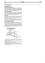
Precautions Correct Use Sensor Mounting Angle If the E4B is in level control or distance control of sensing objects, the stability of signal detection will depend on the sensing surface condition of the objects. Considering the repose angle of the objects, mount the E4B so that the ultrasonic beam and the sensing surface of each object meet at right angles to each other. Surrounding Objects Make sure that the Sensor is free from surrounding objects that reflect the ultrasonic beam diffusion, otherwise the Sensor may malfunction. In particular, pay the utmost attention so that no side lobe...
Abrir o catálogo na página 9
ALL DIMENSIONS SHOWN ARE IN MILLIMETERS. To convert millimeters into inches, multiply by 0.03937. To convert grams into ounces, multiply by 0.03527. In the interest of product improvement, specifications are subject to change without notice. OMRON Corporation Industrial Sensors Division Sensing Devices and Components Division H.Q. 28th Fl., Crystal Tower Bldg. 1-2-27, Shiromi, Chuo-ku, Osaka 540-6028 Japan Phone: (81)6-949-6012 Fax: (81)6-949-6021
Abrir o catálogo na página 12Todos os catálogos e folhetos técnicos OMRON
-
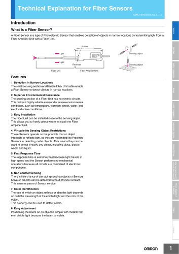 Technical Explanation for Fiber Sensors
14 Páginas
-
 D4F
D4F8 Páginas
-
 D4GS-N
11 Páginas
-
 E4E2
E4E25 Páginas
-
 Smart Laser Sensors E3NC-L/E3NC-S
16 Páginas
-
 Fiber SensorBest Selection Catalog
104 Páginas
-
 Fiber Unit E32-LT/LD
4 Páginas
-
 G9SE Series
20 Páginas
-
 NX-SL/SI/SO
20 Páginas
-
 G9SP
G9SP28 Páginas
-
 G9SX-SM
24 Páginas
-
 G9SX-SM/LM
9 Páginas
-
 G9SX/G9SX-GS
49 Páginas
-
 G9SX-LM
28 Páginas
-
 G9SB
G9SB10 Páginas
-
 G9SA
G9SA16 Páginas
-
 DST1 Series
5 Páginas
-
 WS02-CFSC1-E
3 Páginas
-
 G9SA-300-SC
9 Páginas
-
 K8AK-AS
12 Páginas
-
 K8AK-AW
16 Páginas
-
 K8AK-VS
12 Páginas
-
 K8AK-VW
12 Páginas
-
 K8AK-PH
12 Páginas
-
 K8DS-PH
12 Páginas
-
 K8AK-PM
16 Páginas
-
 K8DS-PM
12 Páginas
-
 K8AK-PA
12 Páginas
-
 K8DS-PA
12 Páginas
-
 K8AK-PW
12 Páginas
-
 K8DS-PU
12 Páginas
-
 K8DS-PZ
12 Páginas
-
 K8AK-TS/PT
12 Páginas
-
 K8AK-LS
12 Páginas
-
 K8AK-TH
12 Páginas
-
 K2CM
K2CM16 Páginas
-
 SE
SE15 Páginas
-
 SAO
SAO13 Páginas
-
 APR-S
APR-S6 Páginas
-
 XS5
XS525 Páginas
-
 XS2
XS229 Páginas
-
 F92A
F92A4 Páginas
-
 GLS
GLS3 Páginas
-
 TL-L
TL-L5 Páginas
-
 V680 series
68 Páginas
-
 V680S Series
68 Páginas
-
 MY
MY35 Páginas
-
 Safety Light Curtain F3SG-R Series
80 Páginas
-
 E3NC-L/-S
16 Páginas
-
 61F-GPN-BT / -BC
5 Páginas
-
 NE1A-SCPU Series
8 Páginas
-
![NE1A-SCPU0[]-EIP](https://img.directindustry.com/pdf/repository_di/15954/ne1a-scpu0-eip-616667_1mg.jpg) NE1A-SCPU0[]-EIP
NE1A-SCPU0[]-EIP8 Páginas
-
 NE0A-SCPU01
6 Páginas
-
 LY
LY14 Páginas
-
![G2R-[]-S](https://img.directindustry.com/pdf/repository_di/15954/g2r-s-616653_1mg.jpg) G2R-[]-S
G2R-[]-S11 Páginas
-
 G7T
G7T7 Páginas
-
 G2A
G2A9 Páginas
-
 G2A-434
7 Páginas
-
 G2AK
G2AK7 Páginas
-
 MK-S
MK-S9 Páginas
-
 MK-S(X)
12 Páginas
-
 MM
MM17 Páginas
-
 MMK
MMK14 Páginas
-
 G4Q
G4Q6 Páginas
-
 G7Z
G7Z9 Páginas
-
 G7J
G7J10 Páginas
-
 E4A-3K
9 Páginas
-
 E4C-UDA
5 Páginas
-
 E6H-C
E6H-C5 Páginas
-
 E6F-C
E6F-C5 Páginas
-
 E6D-C
E6D-C5 Páginas
-
 E6B2-C
5 Páginas
-
 E6A2-C
5 Páginas
-
 NL
NL8 Páginas
-
 VB
VB5 Páginas
-
 SC
SC5 Páginas
-
 D5F
D5F5 Páginas
-
 D5A
D5A8 Páginas
-
 E3S-GS3E4
3 Páginas
-
 E3S-R
E3S-R11 Páginas
-
 E3S-A
E3S-A21 Páginas
-
 E3S-CL
9 Páginas
-
 E3ZM-C
14 Páginas
-
 E3T Data Sheet
26 Páginas
-
 E3T Series
6 Páginas
-
 G5 Series
59 Páginas
-
 Sysmac Catalog
410 Páginas
-
 VT-X700
6 Páginas
-
 E5AC-T
8 Páginas
-
 CP1
CP112 Páginas
-
 CP1E
CP1E12 Páginas
-
 MS4800
40 Páginas
-
 VC-DL100
6 Páginas
-
 FZ4 Series
42 Páginas
-
 ZG2
ZG216 Páginas
-
 ZS Series
32 Páginas
-
 ZW Series
24 Páginas
-
 E9NC-T
2 Páginas
-
 Vision System FH series
54 Páginas
-
 CompoNet
28 Páginas
-
 F3SJ Series Safety Light Curtain
108 Páginas
-
 Code Reader/OCR
24 Páginas
-
 Fiber Sensor Best Selection Catalog
100 Páginas
-
 Portable Multi-logger ZR-RX70
12 Páginas
-
 Air Particle Sensor ZN-PD-S
2 Páginas
-
 Smart Fiber Amplifier Units E3NX-FA
8 Páginas
-
 NT series
18 Páginas
-
 Programmable Controller SYSMAC CVM1
16 Páginas
-
 Round Water-resistant Connectors
31 Páginas
-
 Modular Temperature Controller EJ1
24 Páginas
-
 Safety Controller G9SP
28 Páginas
-
 E3FA PHOTOELECTRIC SENSORS
24 Páginas
-
 Switch Mode Power Supply S8VK-G
22 Páginas
-
 Data Logger ZR-RX Series
12 Páginas
-
 Programmable Terminals NS Series
57 Páginas
-
 DeviceNet Safety System
30 Páginas
-
 Switching Power Supplies
16 Páginas
-
 Photomicro Sensors
7 Páginas
-
 Displacement Sensors
4 Páginas
-
 R87F / R87T AC Axial Fans
28 Páginas
-
 G9SX-GS Safety Guard Switching Unit
28 Páginas
-
 H8PS Cam Positioner
32 Páginas
-
 OS32C Safety Laser Scanner
24 Páginas
-
 FQ Vision Sensor
17 Páginas
-
 UM, MC3 Safety Mat/Safety Mat Controller
19 Páginas
-
 ZN-PD Air Particle Sensor
16 Páginas
-
 ZUV-C20H / C30H Smart Curing System
14 Páginas
-
 E5CC Digital Temperature Controller
38 Páginas
-
 S8EX Switch Mode Power Supply
24 Páginas
-
 CP1L CP series CP1L CPU Unit
36 Páginas
-
 E2EF
E2EF8 Páginas
-
 FQ2 Smart camera
24 Páginas


Catálogos arquivados
-
 SAFETY APPLICATION HANDBOOK
55 Páginas
-
 SMART REMOTE I/O
12 Páginas
-
 Sensor Accessories
38 Páginas
-
 REGULATION SOLUTIONS
24 Páginas
-
 Vision Systems
20 Páginas