
Excertos do catálogo

2601B-PULSE System SourceMeter® 10 ps Pulser/SMU InstrumentDatasheet through highly automated pulsed l-V production test. For automated system applications, the 2601 B-PULSE's Test Script Processor (TSP®) runs complete test programs from inside the instrument for industry-best throughput. In larger, multi-channel applications, the Keithley TSP-Link® technology works together with TSP technology to enable high-speed, pulser/SMU-per-pin parallel testing. Because the 2601B-PULSE offers full isolation that does not require a mainframe, it can be easily reconfigured and re-deployed as your test applications evolve. The new 2601B-PULSE System SourceMeter 10 |us Pulser/SMU Instrument with PulseMeter™ technology is an industry-leading high current/high speed pulser with measure plus the full functionality of a traditional SMU. This new pulser offers leading 10 A current pulse output at 10 V with a pulse width minimum of 10 |us, perfect for testing vertical cavity surface emitting lasers (VCSEL) used in LIDAR and facial recognition, LEDs for lighting and displays, semiconductor device characterization, surge protection testing, and so much more. The pulser's built-in dual 1 Megasample/second (MS/s), 18-bit digitizers make it possible to acquire both pulse current and voltage waveforms simultaneously without the need to use a separate instrument. The 2601B-PULSE is a powerful solution that significantly boosts productivity in applications ranging from benchtop characterization Key Features • Industry leading 10 A @ 10 V, 10 microsecond pulse output • No tuning required; works with inductive loads up to 3 pH • Dual 1 Megasample/second digitizers for high speed I/V pulse measurements (pulser function only) • DC capability up to ±40 V @ ±1.0 A, 40 Watt • TSP technology embeds complete test programs inside the instrument for best-in-class system-level throughput • TSP-Link expansion technology for multi-channel parallel test without a mainframe • USB 2.0, LXI Core, GPIB, RS-232, and digital I/O interfaces • Supported in the Keithley KickStart non-programming software tool SMU (I or V Source) Full DC Operation Pulse Operation: Pulse Width >150 ps, typical Dual Integrating ADCs: One each for V and I Solid-state switch routes either SMU or Pulser to output terminals Safety Interlock Input PULSER (I Source only) DC Bias Pulse Operation: 10 ps < Pulse Width < 500 ps Dual 1 MS/s High-speed ADCs: One each for V and I External Interlock/Connector box included with 2601B-PULSE
Abrir o catálogo na página 1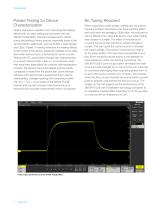
Pulsed Testing for Device Characterization Testing real device operation and minimizing the heating effects with on-wafer testing just got easier with the 2601B-PULSE SMU. Thermal management is critical during the testing of many devices, especially those at the semiconductor wafer level, such as VCSELs, laser diodes, and LEDs. Pulsed I-V testing minimizes the heating effects of the current in the device, especially if tested at the wafer level when devices have no temperature control circuitry. Testing with DC would either change their characteristics, or at worst, destroy them. Later on,...
Abrir o catálogo na página 2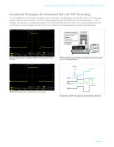
2601B-PULSE System SourceMeter 10 µs Pulser/SMU Instrument Unmatched Throughput for Automated Test with TSP Technology For test applications that demand the highest levels of automation and throughput, the 2601B-PULSE’s TSP technology delivers industry-best performance. TSP technology goes far beyond traditional test command sequencers — it fully embeds, then executes, complete test programs from within the SMU instrument itself. This virtually eliminates the timeconsuming bus communications to and from the PC controller, and thus dramatically improves overall test times. • Conditional...
Abrir o catálogo na página 3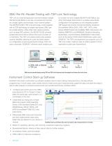
SMU-Per-Pin Parallel Testing with TSP-Link Technology TSP-Link is a channel expansion bus that enables multiple 2601B-PULSE SMUs to be inter-connected and function as a single, tightly-synchronized, multi-channel system. The 2601B-PULSE’s TSP-Link technology works together with its TSP technology to enable high-speed, SMU-perpin parallel testing. Unlike other high-speed solutions, such as large ATE systems, the 2601B-PULSE achieves parallel test performance without the cost or burden of a mainframe. The TSP-Link based system also enables superior flexibility, allowing for quick and easy...
Abrir o catálogo na página 4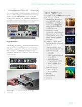
2601B-PULSE System SourceMeter 10 µs Pulser/SMU Instrument Comprehensive Built-in Connectivity Rear panel access to rear-input connectors, remote control interfaces (GPIB, USB 2.0, and LXI/ethernet), D-sub 25-pin digital I/O port (for internal/external trigger signals and handler control), and TSP-Link connectors make it simple to configure multiple instrument test solutions and eliminate the need to invest in additional adapter accessories. Typical Applications I-V functional test and characterization of a wide range of devices, including: • Optoelectronic devices such as vertical cavity...
Abrir o catálogo na página 5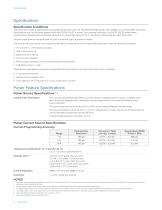
Specifications Specification Conditions This document contains specifications and supplemental information for the 2601B-PULSE System SourceMeter 10 |us Pulser/SMU Instrument. Specifications are the standards against which the 2601B-PULSE is tested. Upon leaving the factory, the 2601B-PULSE meets these specifications. Supplemental and typical values are non-warranted, apply at 23 °C, and are provided solely as useful information. Accuracy specifications are applicable for both normal and High Capacitance modes. The source and measurement accuracies are specified at the terminals of the...
Abrir o catálogo na página 6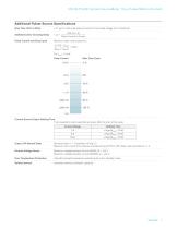
2601B-PULSE System SourceMeter 10 ps Pulser/SMU Instrument <1.7 |js for a full-scale step of current into any load voltage (10 V maximum). Pulse Current (in Amps) Pulse Current and Duty Cycle Maximum duty cycle is given by: 0.3125 - \Ibias\ Pulse Current ±10 A Max. Duty Cycle 3 % ±5 A 6% 0 A Current Source Output Settling Time Time required to reach specified accuracy after the start of the pulse. Current Range Output Off Normal State Electrical short (< 1 0) between HI and LO. Maximum DC current from external sources during OUTPUT OFF state must be limited to <1 A. Remote Voltage Sense...
Abrir o catálogo na página 7Todos os catálogos e folhetos técnicos Keithley Instruments
-
 6220-6221
5 Páginas
-
 6482
64823 Páginas
-
 2520
25208 Páginas
-
 2606B
2606B13 Páginas
-
 AFG1000 Series
13 Páginas
-
 AFG31000 Series Datasheet
22 Páginas
-
 2182A Nanovoltmeter
6 Páginas
-
 6 Series B MSO
69 Páginas
-
 Isolated Measurement Systems
8 Páginas
-
 TBS1000B-EDU Series
14 Páginas
-
 3 Series MDO
36 Páginas
-
 4 Series MSO
40 Páginas
-
 TSG4100A Series
24 Páginas
-
 2461-EC Graphical Potentiostat
16 Páginas
-
 2460-EC Graphical Potentiostats
15 Páginas
-
 2450-EC Graphical Potentiostat
15 Páginas
-
 4200A-SCS Parameter Analyzer
45 Páginas
-
 S540 Power Semiconductor Test System
11 Páginas
-
 6514 Programmable Electrometer
4 Páginas
-
 2460 SourceMeter ® SMU Instrument
14 Páginas
-
 MDO4000C Series Datasheet
43 Páginas
-
 RTPA2A
6 Páginas
-
 TPA-N-PRE Datasheet
4 Páginas
-
 DPO4PWR·MDO3PWR Datasheet
6 Páginas
-
 DPO4LMT/MDO3LMT Datasheet
6 Páginas
-
 DPO7000 Series Datasheet
28 Páginas
-
 SourceXpress® Datasheet
4 Páginas
-
 10G-KR Datasheet
8 Páginas
-
 DPO70000SX Series Datasheet
46 Páginas
-
 AWG4000 Series Datasheet
20 Páginas
-
 TLA6400 Series Datasheet
14 Páginas
-
 Potentiostats 2450-EC
8 Páginas
-
 Series 2268 850W DC Power Supplies
6 Páginas
-
 6487 Picoammeter/ Voltage Source
4 Páginas
-
 6½-Digit USB Digital Multimeter
4 Páginas
-
 7½-Digit Graphical Sampling Multimeter
18 Páginas
-
 4200-SCS
16 Páginas
-
 Model 2750 Multimeter/Switch System
1 Páginas
-
 Model 2450 SMU product brochure
7 Páginas
-
 2013 Keithley product catalog
403 Páginas
-
 Nanotechnology Measurement
13 Páginas
-
 Semiconductor Device Test
11 Páginas
-
 Series 2400 SourceMeter®Family
16 Páginas
-
 USB-Based Data Acquisition Modules
7 Páginas


Catálogos arquivados
-
 8 Series Sampling Oscilloscope
14 Páginas
-
 Multimeter/Switch System
1 Páginas
-
 Keithley’s SourceMeter® Solutions
2 Páginas


