Excertos do catálogo
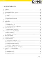
6.1 Pulse Signal :STEP…………………………….…………………………..……………………10 6.2 Direction Signal : DIR……………………………………………………………………………10 6.3 Pulse / Direction Input Timing diagram…………………………………………..……………11 7. Typical Signal Connection……………………………………………………………...…………...12 7.1 Common Positive Connection…………………………………………………………………12 8. Typical Connection of Signal Output………………………………………………………………..13
Abrir o catálogo na página 2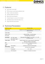
Features / Technical Parameters PWM constant current bipolar subdivision drive Single / double pulse selection Optically isolated input function Motor short circuit protection Compact design, low noise and low vibration Adjustable driving current peak below 3.2 A 2. Technical Parameters STEP Drive model Adapter motor Adapted to two-phase hybrid stepping motor, DS-OLS7 FRS4 Maximum fit 3.2A Power supply Output current Drive mode Input signal Full-bridge bipolar PWM driver IN1(DIR)signal IN2(STEP)signal Output signal Optically isolated output, highest withstand voltage30VDC, Maximum...
Abrir o catálogo na página 3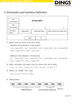
Schematic and Interface Definition 3. Schematic and Interface Definition 1) Signal input (as shown from left to right) Operation mode selection 0: external pulse 1 pin --- pulse STEP +, 2 pin --- pulse STEP-, 3 pin --- direction DIR +, 4 pin --- direction DIR5 feet --- output OUT +, 6 feet --- output OUTOperation mode selection 1: internal pulse Pin 1 --- Input port IN1 +, Pin 2 --- Input port IN1-, Pin 3 --- Input port IN2 +, Pin 4 --- Input port IN2Pin 5 --- Output OUT +, Pin 6 --- Output OUT2) Motor connection and power input (as shown from left to right) 1 pin --- A +, 2 pin --- A- 3...
Abrir o catálogo na página 4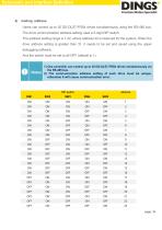
Schematic and Interface Definition 4) mailing address Users can control up to 30 DS-OLS7-FRS4 drives simultaneously using the RS-485 bus. The drive communication address setting uses a 5-digit DIP switch. The address setting range is 1-32, where address 32 is reserved for the system. When the drive address setting is greater than 31, it needs to be set and saved using the upper debugging software. And the switch must be set to all OFF (default is 1). 1) One controller can control up to 30 DS-OLS7-FRS4 drives simultaneously via the RS-485 bus. 2) The communication address setting of each...
Abrir o catálogo na página 5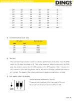
Schematic and Interface Definition 5) Communication baud rate DIP switch 6) Test run The commissioning function is used to verify the performance of the drive. Turn the SW8 switch to ON when the power is off. Then, after power-on, without pulse input, the SW8 gear dial switch is turned from the ON position to the OFF position. After 1 second, the OFF position is set to the ON position, that is, the test run function is started (the motor is at 1 rev/sec. The speed of the cycle is positive and negative movements in a circle). 7) DIP switch (SW9-10) setting Set the terminal resistance to...
Abrir o catálogo na página 6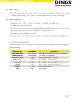
Schematic and Interface Definition 8) Idle current After 500 milliseconds of no pulse input, the current will automatically enter the idle current to reduce motor heating. The current is restored to the set value during pulse input. 9) Indicator function This product has 2 LEDs indicating that the light shows the working status: 1. Green light: (work instructions) When the motor has no current, the lamp flashes 2 times (0.5 second low level, 0.5 second high level) to complete the 2 second high level, and then recirculate. It is always on when the motor is running. The lamp flashes when the...
Abrir o catálogo na página 7
Power Supply The chopper driver continuously changes the size and direction of the motor winding voltage and detects the current to obtain accurate phase current. If both high efficiency and low noise are to be ensured, the driver supply voltage shall be at least 5 times the motor rated phase voltage (that is, the motor rated phase current × phase resistance). If you need the motor to get better high speed performance, you need to increase the driver supply voltage. If power is supplied from a regulated power supply, the supply voltage shall not exceed 48V. If non-stabilized power supply is...
Abrir o catálogo na página 8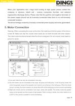
Power Supply When your application has a large load running at high speed, please contact the company in advance, shield anti - reverse connection function, and external regenerative discharge device. Please note that the positive and negative terminals of the power supply should not be inversely connected when there is no anti-inversely connected function. The driver damage caused by inversely connected power supply cannot be guaranteed. 5. Motor Connection Warning: When connecting the motor to the drive, first make sure that the power of the drive is turned off. Make sure that the unused...
Abrir o catálogo na página 9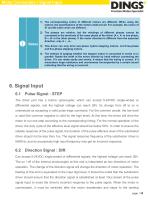
Motor Connection / Signal Input 1) The corresponding colors of different motors are different. When using the motors, the specifications of the motors shall prevail. For example, the colors of 57 and 86 motor wires are different. 2) The phases are relative, but the windings of different phases cannot be connected to the terminals of the same phase of the driver (A +, A- is one phase, B +, B- is the other phase). If the motor direction is different from the expected direction, only A + , A-. 3) This driver can only drive two-phase hybrid stepping motors, not three-phase and five-phase...
Abrir o catálogo na página 10Todos os catálogos e folhetos técnicos Jiangsu DINGS' Intelligent Control Technology Co.
-
 General Catalog
295 Páginas
-
 Simple Brochure
36 Páginas
-
 DS-BVS-FETC-FCAO_Hardware Manual
18 Páginas
-
 DS-BVS-BVM-Series_Reference Manual
181 Páginas
-
 DINGS Servo Studio Manual
57 Páginas
-
 DS-BVM-FETC-FCAO_Hardware Manual
15 Páginas
-
 DS-CL28_42-SA_Text_Technical Manual
49 Páginas
-
 DS-OL42-ICAO_Technical Manual
53 Páginas
-
 DS-OL42-IPD(IRS4)_Technical Manual
26 Páginas
-
 DS-CLS9-FETC-2I_Technical Manual
43 Páginas
-
 DS-CLS9-FETC-2A_Technical Manual
43 Páginas
-
 DS-CLS9-FETC_Technical Manual
17 Páginas
-
 DS-CLS9-FCAO_Technical Manual
59 Páginas
-
 Simple Tuner Pro Quick User Guide
22 Páginas
-
 DS-OLS10-FSC_Technical Manual
12 Páginas
-
 DS-OLS8-FRS4_Technical Manual
30 Páginas
-
 DS-OLS8-FPD_Technical Manual
16 Páginas
-
 DS-OLS4-FPD_Technical Manual
17 Páginas
-
 DS-OLS22_FPD_Technical Manual
16 Páginas
-
 DS-OLS2-FPD_Technical Manual
16 Páginas
-
 DS-CLS9-FRS4_Technical Manual
21 Páginas
-
 DS-CLS9-FRS4-01_Technical Manual
29 Páginas