Excertos do catálogo
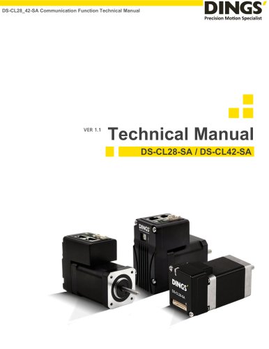
DS-BVS/BVM-Series Reference Manual Reference Manual DS-BVS/BVM-Series
Abrir o catálogo na página 1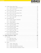
5.4 Profile Velocity Mode (PVM)….…………………………………….………………………35 5.4.1 Profile Velocity Trajectory Generator .…………………………………….………37 5.5 Cyclic Synchronous Torque Mode (CST)…………………………………………………39 5.5.1 5.6 Cyclic Synchronous Velocity Mode (CSV)………………………………………………….42 5.6.1 5.7 Cyclic Synchronous Position Mode (CSP) …………………………………….…………45 5.7.1 5.9 Position Regulation Mode (PRM) …………………………………………………………56 5.9.1 5.10 Velocity Regulation Mode (VRM) ……………………………………………………………58 5.10.1 How to Use VRM……………………………………………………………………..59 5.11 Torque Regulation Mode (TRM) ………………
Abrir o catálogo na página 3
1. Introduction The purpose of this document is to familiarize readers with safe, proper installation and test run of the described device. Follow the guidelines to avoid hazardous situations, improve the device reliability and lifespan, and minimize the installation and test run time. This document provides detailed information about firmware and contains descriptions of the device architecture, device state, operating mode, error handling, and the object.
Abrir o catálogo na página 9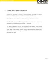
EtherCAT Communication 2. EtherCAT Communication EtherCAT, the abbreviation of Ethernet for Control Automation Technology, is a real-time Ethernet-based fieldbus system created by Beckhoff Automation, Germany. EtherCAT uses a standard Ethernet packet or its slightly modified frame structure. With EtherCAT, the standard Ethernet packet frame no longer has to be received, interpreted, and copied as data to be processed at every node. The fundamental idea of EtherCAT communication is that the slave reads the data addressed to it and processes the data instantaneously while data frame sent from...
Abrir o catálogo na página 10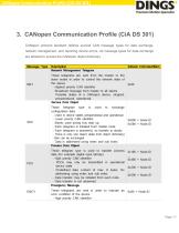
CANopen Communication Profile (CiA DS 301) 3. CANopen Communication Profile (CiA DS 301) CANopen protocol standard defines several CAN message types for data exchange, network management, and reporting device errors. All message types for data exchange are allowed to access the CANopen object dictionary.
Abrir o catálogo na página 11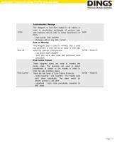
CANopen Communication Profile (CiA DS 301)
Abrir o catálogo na página 12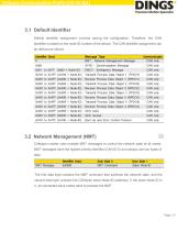
CANopen Communication Profile (CiA DS 301) 3.1 Default Identifier Default identifier assignment involves saving the configuration. Therefore, the CAN identifier is based on the node ID number of the device. The CAN identifier assignment can be defined as follows. 3.2 Network Management (NMT) CANopen master uses multiple MNT messages to control the network state of all nodes. NMT messages have the highest priority identifier (CAN-ID 0) and always use two bytes of data. The first data byte contains the NMT command that switches the network state, and the second data byte contains the CANopen...
Abrir o catálogo na página 13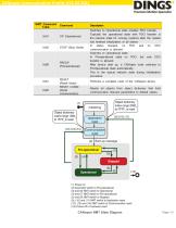
CANopen Communication Profile (CiA DS 301) CANopen NMT State Diagram
Abrir o catálogo na página 14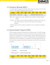
CANopen Communication Profile (CiA DS 301) 3.3 Emergency Message (EMCY) For the Emergency Message, the CANopen device reports any changes in the error state to the bus. The Emergency Message is always 8 byte long. EMCY Code : emergency error code. The EMCY code is defined in the Draft Standard DS301. Error Reg. : error register. The error register is displayed as an object (0x1001) within the device object dictionary. This object is also inserted in the emergency message. A CANopen device sends an emergency message if an error is detected in the setting or resetting. 3.4 Synchronization...
Abrir o catálogo na página 15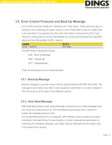
CANopen Communication Profile (CiA DS 301) 3.5 Error Control Protocols and Boot-Up Message Error control protocols enable the monitoring of a node status. These protocols play an important role in switching the system status to a non-critical state in case of a single node or bus line failure. For example, the drive must halt motions in the event of a PLC crash. The Error control protocols use the CAN telegram as a data byte that reports the node NMT status and the CAN identifier 0x700 + Node-Id. The NMT State is reported as follows: - There are three types of error control protocols. 3.5.1...
Abrir o catálogo na página 16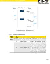
CANopen Communication Profile (CiA DS 301) < Flow diagram of the heartbeat protocol > 3.5.2.1 Consumer Heartbeat Time
Abrir o catálogo na página 17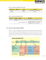
CANopen Communication Profile (CiA DS 301) 3.5.2.2 Consumer Heartbeat Time data 3.5.2.3 Producer Heartbeat Time 3.6 Service Data Object (SDO) SDO is an access to a single object in the object library by using the object index and subindex as an address (also called multiplexer). It always uses 8 data bytes of the CAN message. SDO is always initiated at the CANopen bus master, and the response is taken from the slave node. The basic structure of SDO shows how to use the CAN telegram data bytes.
Abrir o catálogo na página 18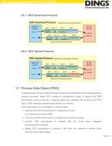
CANopen Communication Profile (CiA DS 301) 3.7 Process Data Object (PDO) CANopen-based Process Data exchange is performed by standard CAN messages without protocol overhead. Each PDO contains a configuration object to specify the PDO transmission mode as well as a mapping object that predefines the content of the PDO data. A PDO message supports data transfer up to 8 bytes. PDO transmission can be initiated in multiple modes. • asynchronous PDO transmission is initiated by an event (e.g. altering the mapped data) • synchronous PDO transmission is initiated by the SYNC message • periodic the...
Abrir o catálogo na página 19Todos os catálogos e folhetos técnicos Jiangsu DINGS' Intelligent Control Technology Co.
-
 Simple Brochure
8 Páginas
-
 General Catalog
354 Páginas
-
 DS-BVS-FETC-FCAO_Hardware Manual
18 Páginas
-
 DINGS Servo Studio Manual
57 Páginas
-
 DS-BVM-FETC-FCAO_Hardware Manual
15 Páginas
-
 DS-CL28_42-SA_Text_Technical Manual
49 Páginas
-
 DS-OL42-ICAO_Technical Manual
53 Páginas
-
 DS-OL42-IPD(IRS4)_Technical Manual
26 Páginas
-
 DS-CLS9-FETC-2I_Technical Manual
43 Páginas
-
 DS-CLS9-FETC-2A_Technical Manual
43 Páginas
-
 DS-CLS9-FETC_Technical Manual
17 Páginas
-
 DS-CLS9-FCAO_Technical Manual
59 Páginas
-
 Simple Tuner Pro Quick User Guide
22 Páginas
-
 DS-OLS10-FSC_Technical Manual
12 Páginas
-
 DS-OLS8-FRS4_Technical Manual
30 Páginas
-
 DS-OLS7-FRS4_Technical Manual
29 Páginas
-
 DS-OLS8-FPD_Technical Manual
16 Páginas
-
 DS-OLS4-FPD_Technical Manual
17 Páginas
-
 DS-OLS22_FPD_Technical Manual
16 Páginas
-
 DS-OLS2-FPD_Technical Manual
16 Páginas
-
 DS-CLS9-FRS4_Technical Manual
21 Páginas
-
 DS-CLS9-FRS4-01_Technical Manual
29 Páginas