
Excertos do catálogo
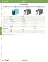
Timers Selection Guide Switches & Pilot Lights Selection Guide Selection Guide Series RTE GT3F 836 Page GT3A 843 851 Signaling Lights Appearance True Power OFF-delay Time Range 0.1 second to 600 hrs 0.1 second to 180 hrs 0.1 to 600 seconds Contact Configuration DPDT SPDT, DPDT SPDT, DPDT Repeat Accuracy ±0.25% maximum ±0.2% maximum ±0.4% maximum 10A, 240V AC SPDT: 3A, 250V AC DPDT: 5A, 240V AC 5A, 250V AC Available Operating Voltage Timers ON-delay Interval OFF-delay One-shot Cycle (off first) Cycle (on first) Signal OFF delay Signal ON/OFF delay Contact Load Rating (resistive) Relays &...
Abrir o catálogo na página 2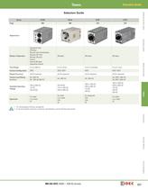
Timers Selection Guide Series GT3W GE1A GT5P GT5Y 856 866 870 Switches & Pilot Lights Selection Guide 875 Page Appearance Signaling Lights Modes of Operation ON-delay ON-delay ON-delay Time Range 0.1s to 300 hrs 0.1s to 10 hrs 0.1s to 10 minutes 0.1s to 1 hour Contact Configuration DPDT SPDT, DPDT SPDT DPDT, 4PDT ±0.2% maximum ±0.2% maximum Relays & Sockets Sequential start ON-delay Recycler and instantaneous Recycler OFF start Recycler ON start Interval Interval ON delay Sequential interval ±0.2% maximum ±0.2% maximum 3A, 250V AC 5A, 120V AC/30V DC 5A, 240V AC 5A, 250V AC 5A, DPDT: 250V AC...
Abrir o catálogo na página 3
Timers Timing Diagrams Overview Switches & Pilot Lights Timing Diagrams Overview Timing Diagrams Overview Guide to Reading Timing Function Diagrams Power Applied Start Input Terminals Shorted Start Input Terminals Opened Power Removed Timer Power 1. If power is disconnected during actual timing, most electronic timers reset to the preset time, ready for the re-application of supply voltage (except for GT3F “true power OFF Delay”). 2. NO = Normally open. 3. NC = Normally closed. NO Contact Closes Signaling Lights Input Signal NC Contact Opens NO Contact Timer Begins Counting NC Contact Set...
Abrir o catálogo na página 4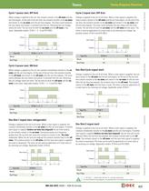
Timers Timing Diagrams Overview Cycle 2 (signal start, OFF first) When voltage is applied to the coil, the contacts remain in the off state and the set time begins. At the end of the set time, the contacts transfer to the on state and remain in the on state until the set time elapses. The timer cycles between the two states until power is removed from the coil. Removing the coil voltage resets the timer. The set time for both the on state and the off state is the same. Applicable models: GT3A-1, -2, -3 and RTE-P(B)1. Voltage is applied to the coil at all times. When a start signal is...
Abrir o catálogo na página 5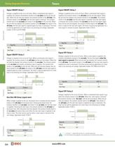
Timers Signaling Lights Switches & Pilot Lights Timing Diagrams Overview Signal ON/OFF-Delay 1 Signal ON/OFF-Delay 2 Voltage is supplied to the coil at all times. When a maintained start signal is supplied, the contacts immediately transfer to the on state and the set time begins. When the set time has elapsed, the contacts transfer to the off state. The contacts remain in the off state until the start signal is removed. The contacts transfer back to the on state and remain in the on state for the set time. When the set time has elapsed, the contacts transfer to the off state and remain in...
Abrir o catálogo na página 6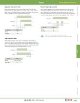
Timers Timing Diagrams Overview Recycler Outputs (power start) When voltage is applied to the coil, both contacts remain in the OFF state and the set time, T1, begins. When T1 has elapsed, output 1 comes on and T2 begins. When T2 has elapsed, output 2 comes on. Both outputs remain on until power is removed from the coil. Applicable model: GT3W-A. When voltage is applied to the coil, both contacts remain in the off state and time T1 begins. When T1 has elapsed, both contacts transfer to the ON state and T2 begins. When T2 has elapsed, both contacts transfer back to the OFF state and T1...
Abrir o catálogo na página 7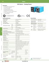
Timers RTE Signaling Lights Switches & Pilot Lights RTE RTE Series — Analog Timers Key features: • 20 time ranges and 10 timing functions • Time delays up to 600 hours • Space-saving package • High repeat accuracy of ± 0.2% • ON and timing OUT LED indicators • Standard 8- or 11-pin and 11-blade termination • 2 form C delayed output contacts • 10A Contact Rating Cert. No. E9950913332316 (EMC, RTE) Cert. No. BL960813332355 (LVD, RTE) UL Listed File No. E66043 General Specifications Contact Ratings Solid state CMOS Circuit Operation Type Relays & Sockets Operation System Multi-Mode Time Range...
Abrir o catálogo na página 8
Timers RTE Switches & Pilot Lights Part Numbering Guide RTE series part numbers are composed of 4 part number codes. When ordering a RTE series part, select one code from each category. Example: RTE-P1AF20 RTE — 1 AF20 l Function Group m Input Voltage Signaling Lights k Terminal Style j Series P Part Numbers: RTE Series Description Part Number Code RTE series j Series Remarks RTE For internal circuits, see next page. Blade B 1 Each function group has different timing functions. ON-delay, cycle OFF, cycle ON, signal ON/ OFF delay, OFF-delay, one-shot 2 See page 832. Select one only. 100 to...
Abrir o catálogo na página 9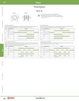
Timers RTE Switches & Pilot Lights Timing Diagrams RTE-P1, -B1 RTE-P1 4 RTE-P1 RTE-P2 external control signal 4 5 3 6 3 2 7 2 8 Signaling Lights 1 (~/+) (~/-) (~/+) 6 6 7 2 8 1 11 4 8 7 3 9 1 2 10 7 A 1 11 3 6 4 1 5 2 6 9 7 4 8 5 9 6 B A 7 8 B 9 7 B A 10 (~/+) (~/-) (~/-) A (~/+) 3 (~/-) 3 (~/+) (~/-) A: ON-Delay 1 (power start) Set timer for desired delay, apply power to coil. Contacts transfer after preset time has elapsed, and remain in transferred position until timer is reset. Reset occurs with removal of power. Item Delayed Contact Terminal Number Operation (1) 1 - 3, 6 - 8 (2) 4 - 7,...
Abrir o catálogo na página 10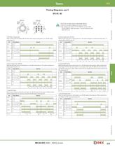
Timers RTE Switches & Pilot Lights Timing Diagrams con’t RTE-P2, -B2 RTE-P1 RTE-P2 external control signal 4 3 2 4 3 1 5 6 67 5 7 8 1 11 (~/+) 4 8 3 9 (~/+) 1 2 3 4 5 6 5 7 6 7 (~/+) (~/-) (~/+) RTE-B2 external control signal 1 2 5 9 6 4 5 6 8B 9 7 8 9 1 5 2 6 9 7 4 8 A 7 A (~/+) (~/-) A B (~/-) (~/+) (~/-) start 3 4 B 8 8 9 2 A 10 1 11 10 (~/-) RTE-B1 RTE-B2 external start control 1 3 signal 2 start B (~/+) (~/-) Terminal Number 1. RTE-P2: Do not apply voltage to terminals #5, #6 & #7. 2. RTE-B2: Do not apply voltage to terminals #2, #5 & #8. 3. IDEC sockets are as follows: RTE-P2:...
Abrir o catálogo na página 11Todos os catálogos e folhetos técnicos IDEC
-
 Web Server Module
2 Páginas
-
 IDEC FL1D SmartRelay
12 Páginas
-
 MicroSmart
28 Páginas
-
 AP22M Series
4 Páginas
-
 IDEC E-S top Switches
6 Páginas
-
 Complete Contactors Catalog
60 Páginas
-
 Circuit Breakers Catalog
12 Páginas
-
 Complete Terminal Blocks Catalog
22 Páginas
-
 Complete Relay & Socket Catalog
76 Páginas
-
 Complete Display Lights Catalog
44 Páginas
-
 Complete Switch & Pilot Device Catalog
252 Páginas
-
 Complete AS-Interface Safety at Work
8 Páginas
-
 Complete Enabling Switches Catalog
20 Páginas
-
 Complete Door Interlock Switches Catalog
94 Páginas
-
 Complete X Series E-Stops Catalog
23 Páginas
-
 Complete Safety Overview
4 Páginas
-
 Sensor catalog
55 Páginas
-
 Complete Power Supply Catalog
20 Páginas
-
 Complete Automation Software Catalog
18 Páginas
-
 Complete O/I Catalog
29 Páginas
-
 Complete PLC Catalog
64 Páginas
-
 All Product Brochure
6 Páginas

