
Excertos do catálogo

Safety Overview XW Series E-Stops Interlock Switches Enabling Switches Safety Control Light Curtains AS-Interface Safety at Work
Abrir o catálogo na página 1
Revolutionary “Safe Break Action” Design The IDEC Emergency Stop switches, the XA, XW, and XN series, include revolutionary new technology that will change the way E-Stop switches are designed. This “safe break action” concept provides greater levels of human safety and is the first of its kind in the world! Conventional E-Stop switches are designed with spring pressure on the Normally Closed (NC) contacts, keeping them in the closed position and allowing the machine to operate. Improper installation or excessive force to the stop button in an emergency may break or dislodge a vital part,...
Abrir o catálogo na página 2
Important Safety Information Overview X Series E-Stops have lower internal energy in the “Locked” (Latching) position than in the “Normal” (Reset) position. When the switch is damaged from an excessive shock, the main contact (NC) moves toward the OFF (Safe) position. Direct Opening Action XW Series E-Stops Even if the contacts are welded, the force applied on the button directly opens the contact. Rated Insulation Voltage: 250V Rated Thermal Current: 2.5A Safety Interlock Mechanism Contacts are opened when the operator is locked, and remain opened until the operator is unlocked...
Abrir o catálogo na página 3
Interlock Switches Selection Guide Series see Switches & Pilot Devices section see Switches & Pilot Devices section Page Mounting Hole Operator Type Illuminated & Non-Illuminated E-Stops: Pushlock/Turn Reset, Push-Pull Reset Action Pushlock Pull or Turn Reset (both actions available in each switch, except XN4E) Contact Configuration Enabling Switches Electrical Life Mechanical Life Termination Degree of Protection Screw Terminals Operator: IP65 (IEC60529) Terminal: IP20 (when XW9Z-VL2MF is installed) AS-Interface Safety at Work Light Curtains Safety Control
Abrir o catálogo na página 4
Operating Force Push-to-lock: 32N Pull-to-reset: 21N Turn-to-reset: 0.27N·m Minimum Force Required for Direct Opening Action Min Operator Stroke Required for Direct Opening Action Maximum Operator Stroke Contact Resistance 50mΩ maximum (initial value) Contact Material Gold plated silver Insulation Resistance Impulse Withstand Voltage Pollution Degree Operation Frequency Shock Resistance Operating extremes: 150m/s2 (15G), Damage limits: 1000m/s2 (100G) Vibration Resistance Operating extremes: 10 to 500Hz, amplitude 0.35mm acceleration 50m/s2 Damage limits: 10 to 500Hz, amplitude 0.35mm...
Abrir o catálogo na página 5
Part Numbers Overview Operator Type Monitor Contact Main Contact Part Number Interlock Switches 40mm Mushroom LED with built-in 24V AC/DC LED 1. The light is independent of the position of the switch, except for push-on LED type. 2. The light only operates when the switch is pressed as it is internally wired. Enabling Switches XW Series EMO Switches Style Part Number FB Enclosures with XW E-Stops Style Part Number Light Curtains AS-Interface Safety at Work 60mm Push-lock Turn/Pull Reset Non-Illuminated 2NC 40mm Push-lock Turn/Pull Reset Illuminated* 40mm Push-lock Turn/Pull Reset...
Abrir o catálogo na página 6
XW Series E-Stops Contact Ratings Mounting Hole Layout Resistive Load (DC-12) 20.1 Inductive Load (DC-13) Gasket Locking Ring Terminal Marking Description • Contact Type 1-2: NC main contact 3-4: NO monitor contact • Contact Number (1-4) Starting with the contact on TOP in a counterclockwise direction. Note: 1: contact on the TOP 2: contact on the Left 3: contact on the Bottom 4: contact on the Right Light Curtains Safety Control Terminal Arrangements (Bottom View) 4NC 1NO-3NC 2NC Voltage Code Blank: Non-illuminated Q4: Illuminated 24V AC/DC Color R: red RH-EMO: red with EMO engraving 1 - 4...
Abrir o catálogo na página 7
XW LED Illuminated/Push-ON (with terminal cover) Illuminated Gasket M3 Terminal Locking Ring Screw M3 Terminal M3 Terminal Screw Screw Gasket Gasket Locking Ring Locking Ring Terminal Cover IP20 Protection Cover XW9Z-VL2M XW9Z-VL2MF Interlock Switches Panel Cut-out Enabling Switches Rubber Gasket Locking Ring Terminal Cover XW9Z-VL2MF Panel Thickness 0.8 to 6 Accessories: Terminal Covers Appearance Safety Control Panel Cut-out Gasket Locking Ring Panel Cut-out Panel Cut-out Panel Thickness 0.8 6 Panel Thickness 0.8 toto 6 Panel Thickness 0.8 to 6 Panel Thickness 0.8 to 6 XW Non-Illuminated...
Abrir o catálogo na página 8
Operating Instructions Installing the Contact Block First unlock the operator button. Grab the bayonet ring j and pull back the bayonet ring until the latch pin clicks k, then turn the contact block counterclockwise and pull out l. First unlock the operator button. Align the small t marking on the edge of the operator with the small s marking on the yellow bayonet ring. Hold the contact block, not the bayonet ring. Press the contact block onto the operator and turn the contact block clockwise until the bayonet ring clicks. Bayonet Ring Removing the Contact Block p marking XW Series E-Stops...
Abrir o catálogo na página 9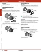
IP20 Protection Terminal Cover XW9Z-VL2MF Screw Terminal 1. Wire thickness: AWG18 to 16 To install the IP20 protection cover, align the TOP marking on the cover with the TOP marking on the contact block, and press the cover toward the contact block. 2. Tighten the M3 terminal screw to a tightening torque of 0.6 to 1.0 N·m. Installing and Removing Terminal Covers Enabling Switches Interlock Switches To install the terminal cover, align the TOP marking on the terminal cover with the TOP marking on the contact block. Place the two projections on the bottom side of the contact block into the...
Abrir o catálogo na página 10
Switches & Pilot Devices ø16mm XA E-Stops Switches & Pilot Devices Signaling Lights Relays & Sockets • Two button sizes: ø29 and ø40mm • Lead-free, RoHS compliant, (EU directive 2002/95/EC) • Depth behind the panel: Standard - only 27.9mm for 1 to 4 contacts Unibody - only 23.9mm for 1NC or 2NC • IDEC’s original “Safe break action” ensures that the NC contacts open when the contact block is detached from the operator. • Push-to-lock, Pull or Turn-to-reset operator • Direct opening action mechanism (IEC60947-5-5, 5.2, IEC60947-5-1, Annex K) • Safety lock mechanism (IEC60947-5-5, 6.2) •...
Abrir o catálogo na página 11Todos os catálogos e folhetos técnicos IDEC USA
-
 LD6A
LD6A8 Páginas
-
 LF2B LED Illumination Units
6 Páginas
-
 LF1B Series LED Illumination Units
4 Páginas
-
 A series Switches & Pilot Lights
40 Páginas
-
 BA Series Terminal Blocks
52 Páginas
-
 EF1A Flameproof LED
24 Páginas
-
 TWS series
40 Páginas
-
 H6 Series
28 Páginas
-
 Complete PLC Catalog
64 Páginas
-
 Complete Automation Software Catalog
18 Páginas
-
 Complete Circuit Breakers Catalog
12 Páginas
-
 Complete Terminal Blocks Catalog
22 Páginas
-
 Complete Timer Catalog
52 Páginas
-
 Complete Relay & Socket Catalog
76 Páginas
-
 Complete Switch & Pilot Device Catalog
252 Páginas
-
 Complete AS-Interface Safety at Work
8 Páginas
-
 Complete Door Interlock Switches Catalog
94 Páginas
-
 Complete Safety Overview
4 Páginas
-
 Complete Power Supply Catalog
20 Páginas
-
 Complete O/I Catalog
29 Páginas
-
 All Product Brochure
6 Páginas


Catálogos arquivados
-
 Lumifa LED Light Catalog
8 Páginas
-
 YC Series Contactors Catalog
24 Páginas
-
 YS Series Contactors Catalog
60 Páginas
-
 Complete Display Lights Catalog
44 Páginas
-
 Complete Enabling Switches Catalog
20 Páginas
-
 All Product Brochure
2 Páginas