Excertos do catálogo
Guide Wheels and Track Technical Guide HepcoMotion.com
Abrir o catálogo na página 1
DUALVEE ® GUIDE WHEELS (OVERVIEW) WHEEL TYPE Original Guide Wheels Carbon PART NUMBER SCHEME APPLICATION CONDITIONS W_ • General purpose • Factory floor conditions W_X Original Guide Wheels Stainless Studded Polymer Wheels Vacuum Wheels • Corrosive conditions APPLICATION EXAMPLES • Automation • Automotive • Woodworking • Printing • Packaging • Paper/textiles BALL RETAINER MATERIAL • Medical • Laboratory • Food & beverage Polymer (overmold) 440C Stainless • Corrosive conditions • Low noise requirements • Electronics • Medical • Laboratory • Vacuum environments • Material science Washdown...
Abrir o catálogo na página 2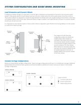
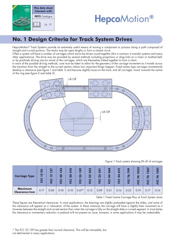
SYSTEM CONFIGURATION AND GUIDE WHEEL MOUNTING Load Orientation and Eccentric Wheels In designing a wheel carriage, it is important to use the right combination and orientation of eccentric and concentric guide wheels. Linear guide systems should always have two concentric wheels and all the other guide wheels should be eccentric. The eccentric wheels are adjusted to remove the play between the wheels and track, equally loading all the wheels so that they roll instead of slide or skid on the track. When the wheel carriage is loaded in the radial direction, the pair of concentric wheels...
Abrir o catálogo na página 3
LIFE AND WEAR RESISTANCE Harsh/Debris-Laden Environments and Wear Resistance Since the circumference of the wheel is greater at the major diameter than at the minor diameter, each rotation creates a variation of velocity on the surface of the wheel. This wheel surface velocity variation results in a constant sweeping action. As such, DualVee® guide wheels are successfully employed in a wide variety of harsh environments, including in the presence of metal chips, powders, fibres, slurries, and other environments. The presence of harsh contaminants will reduce the service life of all types of...
Abrir o catálogo na página 4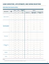
LOAD CAPACITIES, LIFE ESTIMATE, AND SIZING/SELECTION Guide Wheel Load Capacity & Mass WHEEL VARIETY Polymer Overmold Carbon Steel, Stainless Steel, & Food/Pharma BLIND HOLE STUD (SWS…/ SWI...) THROUGH HOLE STUD (SWA...) WHEEL SIZE Solid Lubricant High Temp. & Low Temp. Eccentrically studded or bushed wheels provide adjustability of the wheel to the track. Because of their ability to move and adjust, eccentric wheels are not intended to be the primary carrier of external radial loads. See Wheel Carriage Configurations on page 5.
Abrir o catálogo na página 5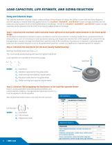
LOAD CAPACITIES, LIFE ESTIMATE, AND SIZING/SELECTION Sizing and Selection Steps The load/life estimation requires a basic understanding of the principles of statics, the ability to work with free body diagrams, and the capacity to resolve externally applied forces on a DualVee®, MadeWell®, and MinVee® based carriage assembly into the radial and axial reaction forces at each guide wheel in the design. The life of a DualVee®, MadeWell®, and MinVee® based carriage assembly will be limited to the life of the most heavily loaded wheel in the design. Step 1: Calculate the resultant radial and...
Abrir o catálogo na página 6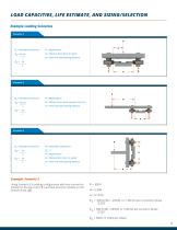
LOAD CAPACITIES, LIFE ESTIMATE, AND SIZING/SELECTION Example Loading Scenarios Scenario 1 F FA = Resultant axial force a = Distance from force to wheel x = Track vee apex spacing distance F FA = Resultant axial force a = Distance from track vee apex to force x = Track vee apex spacing distance F FA = Resultant axial force FR = Resultant radial force a = Distance from force to wheel F = Applied force x = Track vee apex spacing distance Example: Scenario 3 Using Scenario 3's loading configuration with two concentric wheels on the top track ( 1 ) and two eccentric wheels on the bottom track (...
Abrir o catálogo na página 7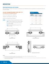
MOUNTING Mounting Dimensions and Formulas When fabricating a DualVee® linear guide from components the following formulas are applicable for mating wheel plate and track plate designs. For sizes 1 through 4XL DualVee® single-edge track with equivalent sized guide wheels: Inboard mounting (see Fig. 1): A = B + X Outboard mounting (see Fig. 2): A = C - X Exterior mounting (see Fig. 3): A = D - Y WHERE A = Distance between wheel plate hole centers B & C = Distance between track reference edges D = Distance between the theoretical sharp of 90° exterior angles DUALVEE® WHEEL SIZE X & Y =...
Abrir o catálogo na página 8
MOUNTING Machining for Mounting Studded Guide Wheels Suggested machining for mounting studded wheels (SWS series and SWI polymer) is shown below: ECCENTRIC STUD HOLE GEOMETRY CONCENTRIC STUD HOLE GEOMETRY C’BORE DIAMETER REMAINING MATERIAL REAMED HOLE DIAMETER REAMED HOLE CHAMFER MINIMUM THICKNESS
Abrir o catálogo na página 9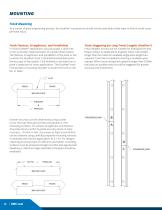
MOUNTING Track Mounting As a matter of good engineering practice, the DualVee® components should not be used where their wear or failure could cause personal injury. Track Flatness, Straightness, and Parallelism In most DualVee® applications, accuracy plays a small role in the successful implementation of a guide wheel system. The flatness, straightness, and parallelism of the plate or bar to which the DualVee® track is attached (bolted) determine the accuracy of the system. Cold finished or extruded bar or plate is adequate for many applications. The DualVee® track incorporates a mounting...
Abrir o catálogo na página 10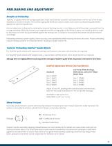
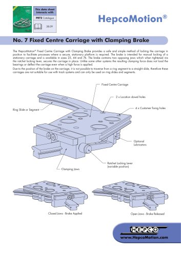
PRELOADING AND ADJUSTMENT Benefits of Preloading Typically, in a guide wheel and carriage application, there should be two concentric mounted wheels and the rest of the wheels should be on eccentric mounts. The eccentric type guide wheels are used to create a cam action to preload the guide wheels against one side of the guide track. Normal adjustment is obtained by rotating the eccentric bushing, journal, or stud feature until all free play is removed from the carriage assembly. When the eccentrics are adjusted and the carriage plate is held firmly in place, one should be able to rotate by...
Abrir o catálogo na página 11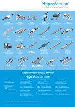
Linear Guidance and Transmission System Sealed Belt Drive Heavy Duty Slide System Ring Slides and Track System Aluminium Frame and Machine Construction System Heavy Duty Driven Linear System Hepco Ball Screws Heavy Duty Track Roller Guidance System Precision Steel and Aluminium Shaft Driven Track System Stainless Steel Based Slide System Linear Transmission and Positioning System Telescopic Ball Bearing Slides Profile Driven Unit Vee Slide Linear Guidance Systems Ball Bushings Linear Bearing System Heavy Duty Ring Slides and Track System Single Edge Slide System Aluminium Based Slide System...
Abrir o catálogo na página 12Todos os catálogos e folhetos técnicos HepcoMotion
-
 HLG Hepco Linear Ball Guides
17 Páginas
-
 SBD Sealed Belt Drive
11 Páginas
-
 MFS machine fencing system
6 Páginas
-
 HGS gantry solutions
9 Páginas
-
 HDS2 Heavy Duty Slide System
27 Páginas
-
 DLS V Guide-based Linear Actuator
32 Páginas
-
 DTS2 Dynamic Track Systems
8 Páginas
-
 PRT2 No. 2 Installation Details
10 Páginas
-
 PRT2 No. 3 Load Life Information
8 Páginas
-
 PRT2 No. 4 Single Edge Track Systems
4 Páginas
-
 PRT2 No.8 DTS Components
19 Páginas
-
 PRT2 No. 10 Slip Block Adjustment
4 Páginas
-
 PRT2 No. 11 Mix & Match
3 Páginas
-
 PRT2 1-Trak
8 Páginas
-
 Floating Bearings
2 Páginas
-
 CHK Controlled Height Bearings
3 Páginas
-
 DualVee Wash Down Wheels
2 Páginas
-
 GV3 Linear Guide System Technical Guide
30 Páginas
-
 PRT2 No. 5 Moment Load Carriages
9 Páginas
-
 MCS Catalogue
36 Páginas
-
 Profiles with Linear Guides
8 Páginas
-
 ALR Aluminium Rings
4 Páginas
-
 HTS Drawer Slides Catalogue
40 Páginas
-
 MHD Catalogue
8 Páginas
-
 PSD80 Light Weight Ball Screw Actuator
12 Páginas
-
 PSD80 No.1 Ballscrew
6 Páginas
-
 HDRT Heavy Duty Ring and Tracks
13 Páginas
-
 Uni-Guide – Product Overview
4 Páginas
-
 ZIMM GSZ & Z Series Screw Jacks
196 Páginas
-
 System Solutions and Motion Control
6 Páginas


Catálogos arquivados
-
 BSP Ballscrew Premier
9 Páginas
-
 vee slide linear guidance system
8 Páginas
-
 PDU2 aluminium profile driven unit
5 Páginas
-
 LoPro aluminium based slide system
60 Páginas
-
 SL2 Stainless Steel Slide System
15 Páginas
-
 Vacuum Bearing Datasheet 02 UK
4 Páginas
-
 PRT2 No.6 Bleed Lubrication
8 Páginas
-
 DualVee Guide Wheels Catalogue
11 Páginas
-
 MCS – RapiLok
2 Páginas
-
 ZIMM – Z Series Leaflet
4 Páginas
-
 THE TOUGHEST LINEAR/ROTARY BEARING
6 Páginas