Excertos do catálogo

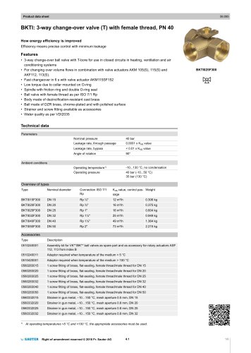
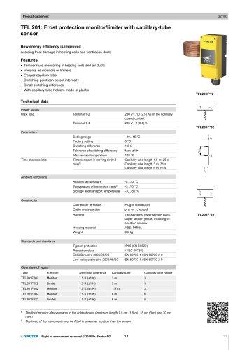
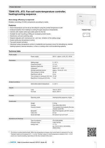
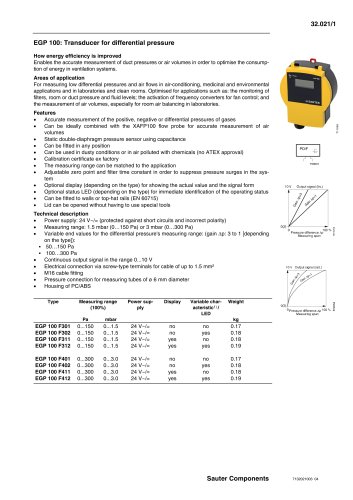
Product data sheet TFL 611: Continuous frost monitor with capillary sensor How energy efficiency is improved Demand-controlled, large-area monitoring of system components with active capillary sensor Features • Detects the lowest temperature that occurs for a length of at least 250 mm at any position along the capillary tube • Used on air side in ventilation and air conditioning units where protective measures must be taken against freezing • Active capillary sensor for measuring the lowest temperatures in the range 0...15 °C • Vapour-filled capillary tube and diaphragm system with inductive system of measurement • Setting range 1...10 °C • Start-up function • LED and 7-segment display • Self-monitoring of sensor line Technical data Power supply Power consumption Frequency Measuring range Setting range Adjustment point Accuracy for adjustment point Switching difference Temperature for capillary tube Time constant in still air Time constant in moving air Response length for capillary tube Inputs/Outputs Admissible cable length Analogue input Valve control for terminal Y Analogue outputs Sensor temperature for terminal B Valve control for terminal Y10 Ambient conditions Operation Potential-free relay outputs (Q terminals) Humidity (non-condensing) Humidity (non-condensing) Terminals with spring technology Cable inlet Cable gland M16 for cable diameter 5...10 mm SELV/PELV: Safety Extra Low Voltage/Protected Extra Low Voltage No earth conductor necessary Right of amendment reser
Abrir o catálogo na página 1
Product data sheet Housing cover Capillary tube Vibration resistance Overview of types Type Continuous frost monitor; 0...15 °C; capillary tube length= 2m Continuous frost monitor; 0...15 °C; capillary tube length= 6m Accessories Type Set for duct fitting consisting of: 5 capillary-tube holders, 1 depth-adjustable flange Five holders for fitting the capillary tube Depth-adjustable flange Intended use This product is only suitable for the purpose intended by the manufacturer, as described in the “Description of operation” section. All related product regulations must also be adhered to....
Abrir o catálogo na página 2
Product data sheet Start-up function The frost signal is added to the valve control signal connected to signal input Y. The effect of this is that before the output relay is switched to the “Frost” position (Q11/Q12), the heating valve is opened fully via signal output Y10. This switching prevents the system from turning on and off multiple times when it starts up. To ensure that the lowest temperature is always detected at the capillary tube, the temperature of the diaphragm box in the interior of the housing must always be above the capillary temperature. This is performed by the...
Abrir o catálogo na página 3
Product data sheet the frost monitor falsely detects a low temperature and goes into the “Frost” position. The same applies to a power failure or the failure of important electronic switching components. In the case of larger air duct diameters, the monitoring of a heating coil can be performed with multiple TFL 611 via: • Series connection of the TFL 611 valve control signal outputs/inputs • Series connection of the TFL 611 relay contacts Note If the relay contacts (Q11/Q12/Q14) are being operated with low voltage (U > 50 V), the following conditions apply: • For adjustment work, the...
Abrir o catálogo na página 4
Product data sheet Disposal When disposing of the product, observe the currently applicable local laws. More information on materials can be found in the Declaration on materials and the environment for this product. Connection diagram System null, measuring null Measuring signal output = 0...10 V ≙ 0...15 °C Signal input for controller valve control signal = 0…10 V Signal output for valve control = 0…10 V Relay contacts ~ 12...250 V Min 100 mA, max 6(2) A Relay contacts = 12...24 V Min 100 mA, max 6A Dimension drawing Right of amendment reserved © 2015 Fr. Sauter AG
Abrir o catálogo na página 5
Product data sheet Fr. Sauter AG Im Surinam 55 CH-4016 Basel Tel. +41 61 - 695 55 55 www.sauter-controls.com Right of amendment reserved © 2015 Fr. Sauter AG
Abrir o catálogo na página 6Todos os catálogos e folhetos técnicos Fr. Sauter AG
-
 SAUTER Catalogue
551 Páginas
-
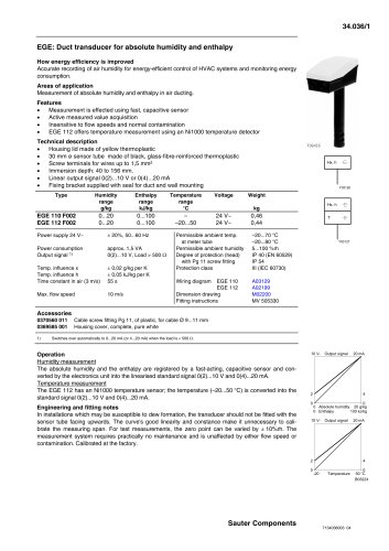
 EGE 112: Duct transducer, enthalpy
3 Páginas
-
 HSC 120: Room humidistat
3 Páginas
-
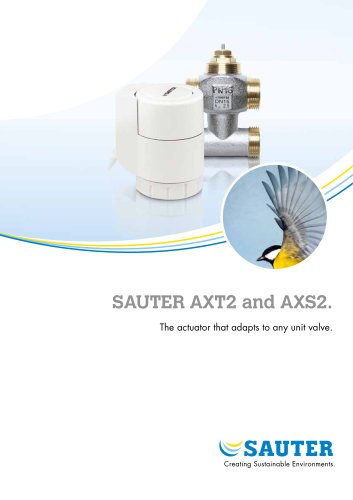 SAUTER AXT2 and AXS2.
8 Páginas
-
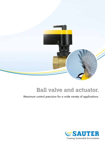 Ball valve and actuator.
6 Páginas
-
 SAUTER Valveco compact
8 Páginas
-
 Valves and actuators.
32 Páginas
-
 AVM 322S-R: Retrofit actuator
8 Páginas
-
 SAUTER vialoq AVM 100
2 Páginas
-
 ASM 134: Damper actuator
4 Páginas
-
 SAUTER flexotron ® 400
4 Páginas
-
 EXG: Active potentiometer
2 Páginas
-
 flexotron ® 2000
2 Páginas
-
 ESL: Electronic power control unit
3 Páginas
-
 SAUTER flexotron800
8 Páginas
-
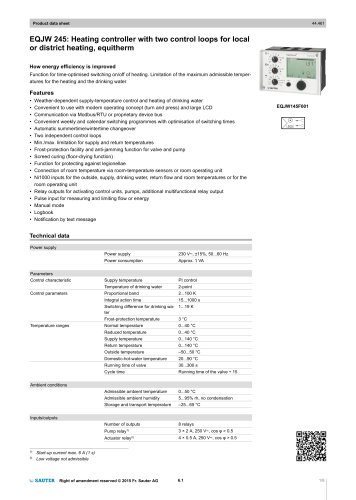 EQJW 24
8 Páginas
-
 SAUTER equitherm ® EQJW125/EQJW135
4 Páginas
-
 NRT 101
8 Páginas
-
 Thermowells
6 Páginas
-
 Indoor air quality
8 Páginas
-
 SAUTER EGQ
4 Páginas
-
 DSU, DSI: Pressure transmitter
4 Páginas
-
 SAUTER equiflex ® NRT300
4 Páginas
-
 HBC: Humidistats for duct mounting
2 Páginas
-
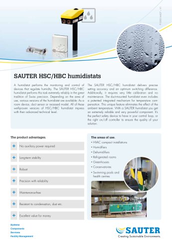 SAUTER HSC/HBC humidistats
2 Páginas
-
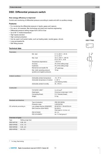 DSD: Differential pressure switch
4 Páginas
-
 DSA: Pressure switch
4 Páginas
-
 TFL 201
3 Páginas
-
 TUC: Universal thermostat
5 Páginas
-
 TLC
TLC2 Páginas
-
 TSHK 670...67
3 Páginas
-
 TSHK 621...643
4 Páginas
-
 TSO, TSH: Room thermostat
4 Páginas
-
 RAK: Universal thermostat
5 Páginas
-
 SAUTER FACTS
28 Páginas
-
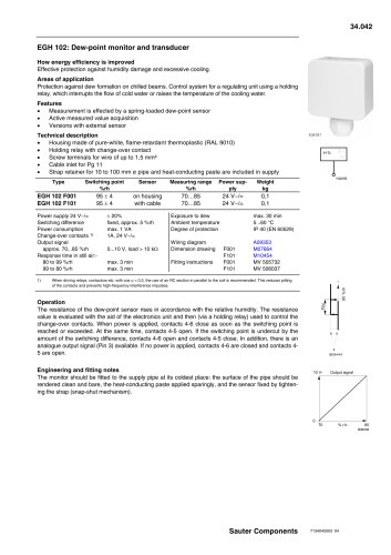 Dew-point monitor and transducer
2 Páginas
-
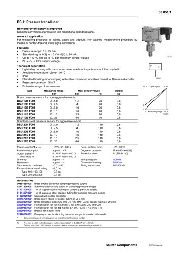 Pressure transducer
3 Páginas
-
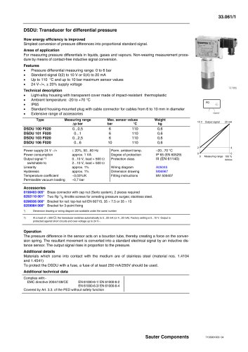 Transducer for differential pressure
2 Páginas
-
 Air-flow transducer
2 Páginas
-
 Transducer for differential pressure
7 Páginas