
Excertos do catálogo
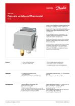
ENGINEERING TOMORROW Data sheet Pressure switch and Thermostat KPS A high level of enclosure Adjustable differential The KPS Series consists of a series of pressure and temperature controlled switches. In this series, special attention has been given to meeting demands for a high level of enclosure, robust and compact construction, and resistance to shock and vibration. For KPS pressure switches the position of the contacts depends on the pressure in the inlet connection and the set scale value. For KPS thermostats the position of the contacts depends on the temperature of the sensor and the set scale value. The series covers most outdoor as well as indoor application requirements and is suitable for use in monitoring alarm and control systems in factories, diesel plants, compressors, power stations and on board ships. Robust and compact construction Resistance to shock and vibration Available with all major marine approvals Approvals CE-marked in accordance with: Underwriters Laboratories Inc., US-UL (excluding (EN 60947-1, EN 60947-4-1, EN 60947-5-1) China Compulsory Certificate, CCC Ship approvals American Bureau of Shipping, ABS Det Norske Veritas, DnV Germanischer Lloyd, GL Registro Italiano Navale, RINA (KPS 43, KPS 45, KPS 47, KPS 76, KPS 77, KPS 79, KPS 80, KPS 81, KPS 83) Maritime Register of Shipping, RMRS Nippon Kaiji Kyokai, NKK (KPS 31, KPS 33, KPS 35, KPS 37, KPS 39, KPS 43, KPS 45, KPS 47) China Classification Society, CCS Bureau Veritas, BV Korean Register of Shipping, KR (KPS 35, KPS 37, KPS 39, KPS 43, KPS 45, KPS 47) Lloyds Register of Shipping, LR
Abrir o catálogo na página 1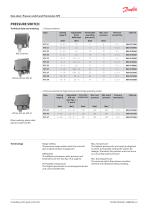
Data sheet | Pressure switch and Thermostat, KPS Technical data and ordering 2. Pressure switches for high pressure and strongly pulsating media When ordering, please state type and code number Range setting The pressure range within which the unit will give a signal (contact changeover). Differential The difference between make pressure and break pressure (see also fig. 5 & 6, page 6). Permissible overpressure The highest permanent or recuiring pressure the unit can be loaded with. Max. test pressure The highest pressure the unit may be subjected to when, for example, testing the system...
Abrir o catálogo na página 3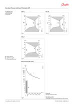
Data sheet | Pressure switch and Thermostat, KPS Technical data and ordering (continued) A: Range setting B: Differential scale C: Obtained differential Fig. 3 Direct current (DC) -load Curve A: gives the maximum load Hatched area B: Acceptable load for the gold plating of the contact IC.PD.P10.I6.02 | 520B7855 |
Abrir o catálogo na página 5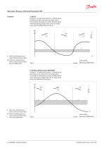
Data sheet | Pressure switch and Thermostat, KPS Function 1. KPS 31 Contacts 1-2 make and contacts 1-4 break when the pressure falls under the set range value. The contacts changeover to their initial position when the pressure again rises to the set range value plus the differential (see fig. 5). [bar] I. Alarm for falling pressure given at the set range value II. Alarm for rising pressure given at the set range value plus the differential. Scale setting Mechanical differential 2. All other KPS pressure SWITCHES Contacts 1-4 make and contacts 1-2 break when the pressure rises above the set...
Abrir o catálogo na página 6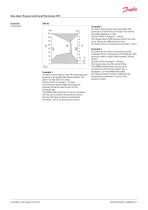
Data sheet | Pressure switch and Thermostat, KPS Function (continued) Fig. 7 Example 1 An alarm must be given when the lubricating oil pressure in an engine falls below 0.8 bar. The alarm is in the form of a lamp. Choose a KPS 31 (range 0 – 2.5 bar). The minimum permissible lubricating oil pressure of 0.8 bar must be set on the range spindle. The differential is fixed at 0.1 bar, i.e. the alarm will not cut out before the pressure rises to 0.9 bar. The lamp must be connected to terminals 1 and 2 in the pressure switch. Example 2 An alarm must be given by a bell when the pressure in a boiler...
Abrir o catálogo na página 7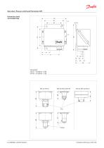
Data sheet | Pressure switch and Thermostat, KPS Dimensions [mm] and weights [kg] Net weight: KPS 31 – 39 approx. 1.0 kg KPS 43 – 47 approx. 1.3 kg
Abrir o catálogo na página 8
Data sheet | Pressure switch and Thermostat, KPS
Abrir o catálogo na página 9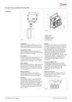
Fig. 8 1. Range spindle 2. Range scale 3. Differential spindle 4. Differential scale 5. Locking screw Installation KPS pressure switches are fitted with a 3 mm steel mounting plate. The units should not be allowed to hang from the pressure connection. Pressure connection When fitting or removing pressure lines, the spanner flats on the pressure connection should be used to apply counter-torque. Steam plant To protect the pressure element from excessive heat, the insertion of a water-filled loop is recommended. The loop can, for example, be made of 10 mm copper tube as shown in fig. 8. Water...
Abrir o catálogo na página 10
When ordering, please state type and code number Electrical connection KPS thermostats are fitted with a Pg 13.5 screwed cable entry suitable for cables from 5 - 14 mm. Contact function is shown in fig. 11
Abrir o catálogo na página 11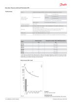
*) Scale values are indicative only. Results given in table are measured in laboratory conditions for factory set values (scale center). The scale accuracy for min and max positions could differ significantly. There are many factors which could influence on product working and scale accuracy. Curve A: gives the maximum load Hatched area B: Acceptable load for the gold plating of the contact
Abrir o catálogo na página 12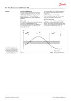
Data sheet | Pressure switch and Thermostat, KPS Function Selection of differential To ensure that the plant functions properly, a suitable differential is necessary. Too small a differential will give rise to short running periods with a risk of hunting. Too high a differential will result in large temperature variations. Differentials The mechanical differential is the differential that is set by the differential spindle in the temperature control. The thermal differential (operating differential) is the differential the system operates on. The thermal differential is always greater than...
Abrir o catálogo na página 13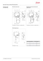
Data sheet | Pressure switch and Thermostat, KPS KPS with rigid sensor Sensor pocket length "A"
Abrir o catálogo na página 14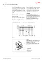
Data sheet | Pressure switch and Thermostat, KPS Installation Installation Location of unit: KPS thermostats are designed to withstand the shocks that occur, e.g. in ships, on compressors and in large machine installations. KPS thermostats with remote sensor are fitted with a base of 3 mm steel plate for fixing to bulkheads, etc. KPS thermostats with bulb sensor are self-supporting from the sensor pocket. Resistance to media Material specifications for sensor pockets: Sensor pocket, brass The tube is made of Ms 72 to DIN 17660, the threaded portion of So Ms 58Pb to DIN 17661. Sensor pocket,...
Abrir o catálogo na página 16Todos os catálogos e folhetos técnicos Danfoss Industrial Automation
-
 Pressure Transmitter Type MBS 9200
7 Páginas
-
 Pressure switch Type RT
21 Páginas
-
 Solenoid valve Type EV310A
11 Páginas
-
 Temperature sensor Type MBT 3270
9 Páginas
-
 Pressure switch RT
17 Páginas
-
 MBC 5000 and MBC 5100
6 Páginas
-
 Pressure switch and Thermostat CAS
16 Páginas
-
 Wind Power
8 Páginas
-
 Pressure switch Type BCP
7 Páginas
-
 Danfoss Link™
14 Páginas
-
 Thermostatic Radiator Valve,
12 Páginas
-
 Optyma™ High Ambient 52 Pack
22 Páginas
-
 Electric Heating
40 Páginas
-
 Hydronic Specialties
48 Páginas
-
 Optyma™ Semi-Hermetic
22 Páginas
-
 Optyma™
60 Páginas
-
 Supermarkets
28 Páginas
-
 Hydronic Balancing & Control
12 Páginas
-
 HGM-PGM Gas detector
4 Páginas
-
 Danfoss Link & Living Connect
4 Páginas
-
 Danfoss Bond Buff er P3
2 Páginas
-
 Automotive Power Modules
4 Páginas
-
 H1 060 Bent Axis Variable Motor
2 Páginas
-
 Danfoss Product catalogue
68 Páginas
-
 AK-PC 772Mini-booster
2 Páginas
-
 Danfoss Service Thermostats
2 Páginas
-
 Danfoss Drives Fieldbus Solutions
12 Páginas
-
 Clean Grid Solutions
44 Páginas
-
 Type EV210A
10 Páginas
-
 Industrial sensors and switches
12 Páginas
-
 Industrial hydraulic applications
8 Páginas
-
 Marine applications
12 Páginas
-
 Mobile Hydraulic applications
12 Páginas
-
 Pressure transmitters overview
2 Páginas
-
 Temperature sensors overview
2 Páginas
-
 Switches overview
2 Páginas


Catálogos arquivados
-
 Fluid controls overview
5 Páginas
-
 How to use - Solenoid valves
46 Páginas
-
 Core Products Catalogue
171 Páginas