
Excertos do catálogo
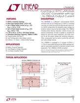
LTM8045 Inverting or SEPIC µModule DC/DC Converter with Up to 700mA Output Current DESCRIPTION FEATURES SEPIC or Inverting Topology n Wide Input Voltage Range: 2.8V to 18V n Up to 700mA Output Current at V = 12V, IN VOUT = 2.5V or –2.5V n Up to 375mA Output Current at V = 12V, IN VOUT =15V or –15V n 2.5V to 15V or –2.5V to –15V Output Voltage n Selectable Switching Frequency: 200kHz to 2MHz n Programmable Soft-Start™ n User Configurable Undervoltage Lockout n 6.25mm × 11.25mm × 4.92mm BGA Package The LTM®8045 is a µModule® (micromodule) DC/DC converter that can be configured as a SEPIC or inverting converter by simply grounding the appropriate output rail. In a SEPIC configuration the regulated output voltage can be above, below or equal to the input voltage. The LTM8045 includes power devices, inductors, control circuitry and passive components. All that is needed to complete the design are input and output capacitors, and small resistors to set the output voltage and switching frequency. Other components may be used to control the soft-start and undervoltage lockout. n The LTM8045 is packaged in a compact (6.25mm × 11.25mm) overmolded ball grid array (BGA) package suitable for automated assembly by standard surface mount equipment. The LTM8045 is RoHS compliant. APPLICATIONS Battery Powered Regulator Local Negative Voltage Regulator n Low Noise Amplifier Power n n L, LT, LTC, LTM, Linear Technology, the Linear logo, µModule and PolyPhase are registered trademarks and Soft-Start is a trademark of Linear Technology Corporation. All other trademarks are the property of their respective owners. TYPICAL APPLICATION Use Two LTM8045s to Generate ±5V Maximum Output Current vs Input Voltage LTM8045 VOUT– VIN RUN SS SYNC 700 22µF FB RT 130k VOUT+ GND LTM8045 600 500 400 • • ±2.5VOUT ±3.3VOUT ±5VOUT ±8VOUT ±12VOUT ±15VOUT 300 200 VOUT– VIN 100 RUN SS 100µF FB 2 4 6 8 10 12 14 INPUT VOLTAGE (V) 16 18 8045 TA01b RT 115k 800 60.4k OUTPUT CURRENT (mA) 4.7µF VOUT –5V • • VIN 2.8VDC TO 18VDC VOUT+ SYNC GND 45.3k VOUT 5V 8045 TA01b 8045fa For more information www.linear.com/8045 1
Abrir o catálogo na página 1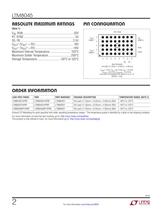
ABSOLUTE mnximum RRTIRGS 9 VALUES DETERMINED PER JEDEC 51-9, 51-12 ORD€R mFORfflRTIOn Consult LTC Marketing for parts specified with wider operating temperature ranges. *The temperature grade is identified by a label on the shipping container. For more information on lead free part marking, go to: http://www.linear.com/leadfree/ This product is only offered in trays. For more information go to: http://www.linear.com/packaging/ ^^^J TECHNOLOGY
Abrir o catálogo na página 2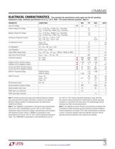
The • denotes the specifications which apply over the full operating temperature range, otherwise specifications are at TA = 25°C. RUN = 12V unless otherwise specified. (Note 2) Note 1: Stresses beyond those listed under Absolute Maximum Ratings may cause permanent damage to the device. Exposure to any Absolute Maximum Rating condition for extended periods may affect device Note 2: The LTM8045E is guaranteed to meet performance specifications from 0°C to 125°C. Specifications over the -40°C to 125°C internal temperature range are assured by design, characterization and correlation with...
Abrir o catálogo na página 3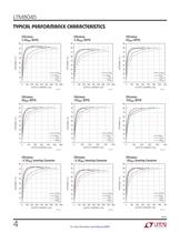
TVPICRL p€RFORmnnc€ CHnnncTCMSTics
Abrir o catálogo na página 4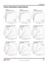
TVPICRL p€RFORmnnc€ CHnnncTCMSTics Input Current vs Output Current, Input Current vs Output Current, Input Current vs Output Current, Input Current vs Output Current, Input Current vs Output Current, Input Current vs Output Current, 8VQUT SEPIC 12VQUT SEPIC 15VQUT SEPIC OUTPUT CURRENT (mA) OUTPUT CURRENT (mA) OUTPUT CURRENT (mA) TECHNOLOGY For more information www.linear.com/8045
Abrir o catálogo na página 5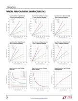
TVPICRL p€RFORmnnc€ CHnnncTCMSTics Input Current vs Output Current, Input Current vs Output Current, Input Current vs Output Current, Input Current vs Output Current, Input Current vs Output Current, Input Current vs Output Current, Input Current vs Input Voltage, Input Current vs Input Voltage, Output Shorted Output Current vs Input Voltage, Output Shorted
Abrir o catálogo na página 6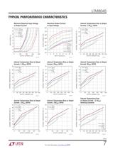
TVPICRL p€RFORmnnc€ CHnnncTCMSTics Minimum Required Input Voltage Maximum Output Current Internal Temperature Rise vs Output vs Output Current vs Input Voltage Current, 2.5V0UT SEPIC OUTPUT CURRENT (mA) INPUT VOLTAGE (V) OUTPUT CURRENT (mA) Internal Temperature Rise vs Output Internal Temperature Rise vs Output Internal Temperature Rise vs Output Internal Temperature Rise vs Output Internal Temperature Rise vs Output Internal Temperature Rise Inverting Converter TECHNOLOGY For more information www.linear.com/8045 *
Abrir o catálogo na página 7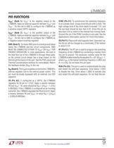
LTM8045 PIN FUNCTIONS VOUT– (Bank 1): VOUT– is the negative output of the LTM8045. Apply an external capacitor between VOUT+ and VOUT–. Tie this net to GND to configure the LTM8045 as a positive output SEPIC regulator. VOUT+ (Bank 2): VOUT+ is the positive output of the LTM8045. Apply an external capacitor between VOUT+ and VOUT–. Tie this net to GND to configure the LTM8045 as a negative output inverting regulator. GND (Bank 3): Tie these GND pins to a local ground plane below the LTM8045 and the circuit components. GND MUST BE CONNECTED EITHER TO VOUT+ OR VOUT– FOR PROPER OPERATION. In...
Abrir o catálogo na página 9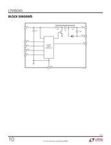
BLOCK DinGftnm ^^^J TECHNOLOGY
Abrir o catálogo na página 10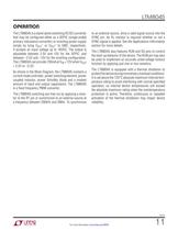
LTM8045 OPERATION The LTM8045 is a stand-alone switching DC/DC converter that may be configured either as a SEPIC (single-ended primary inductance converter) or inverting power supply simply by tying VOUT– or VOUT+ to GND, respectively. It accepts an input voltage up to 18VDC. The output is adjustable between 2.5V and 15V for the SEPIC, and between –2.5V and –15V for the inverting configuration. The LTM8045 can provide 700mA at VIN = 12V when VOUT = 2.5V or –2.5V. As shown in the Block Diagram, the LTM8045 contains a current mode controller, power switching element, power coupled inductor,...
Abrir o catálogo na página 11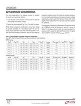
nppucnTions inFORmnnon For most applications, the design process is straight forward, summarized as follows: 1. Look at Table 1 and find the row that has the desired input range and output voltage. 2. Apply the recommended CIN, COUT. F>FB and Rj values. While these component combinations have been tested for proper operation, it is incumbent upon the user to verify proper operation over the intended system's line, load and environmental conditions. Bear in mind that the Table 1. Recommended Component Values and Configuration (Tfl = 25°C. See the Typical Performance Characteristics for Load...
Abrir o catálogo na página 12Todos os catálogos e folhetos técnicos ADI
-
 LTC2068
30 Páginas
-
 LTC6373
34 Páginas
-
 ADL9006
16 Páginas
-
 ADL8104
23 Páginas
-
 AD4115
52 Páginas
-
 ADUM7702
22 Páginas
-
 AD7383
33 Páginas
-
 AD7384
33 Páginas
-
 AD4114
49 Páginas
-
 ADUM7704
22 Páginas
-
 AD7134
86 Páginas
-
 LTspice IV
53 Páginas
-
 New Products Catalog
43 Páginas
-
 RF/IF Amplifiers
9 Páginas
-
 SAR ADC Drivers
2 Páginas
-
 Products for Harsh Environments
4 Páginas
-
 SmartMesh Brochure
8 Páginas
-
 INDUSTRIAL SIGNAL CHAIN
24 Páginas
-
 AUTOMOTIVE ELECTRONIC SOLUTIONS
48 Páginas
-
 µModule® Power Product Family
7 Páginas
-
 Battery Management Solutions
32 Páginas
-
 High Performance DC/DC Controllers
20 Páginas
-
 DC/DC uModule Power Products
32 Páginas
-
 Wireless & RF Solution
36 Páginas
-
 LT2940 - Power and Current Monitor
24 Páginas
-
 LT6656 - 1
18 Páginas
-
 LT3596 - 60V Step-Down LED Driver
22 Páginas


Catálogos arquivados
-
 Automotive & Transportation Solutions
56 Páginas
-
 New Products Catalog
39 Páginas
-
 High Performance DC/DC Controllers
21 Páginas
-
 Power Management for Portable Products
32 Páginas
-
 Power Management for LEDs
24 Páginas
-
 High Speed ADC Products Brochure
14 Páginas