- Catalogs
- ZZ DRIVE TECH
- Catalogue Bevelgearboxes ZZ-Universal-Line®
Catalogue Bevelgearboxes ZZ-Universal-Line®
1 /21Pages

Catalogue Bevelgearboxes ZZ-Universal-Line®
1 /21Pages
Catalog excerpts


Contents Bevel Gear Units Today, the ZZ-Antriebe Company is proud of its 90 years of experience in the field of drive system engineering, combined with intensive innovation and progress. We are devoted to the development, planning, construction and production of custom-designed products according to latest technical standards. ZZ products can be found in all areas of machine and plant construction both inland and overseas, throughout the world. Our objectives of manufacturing high quality products take top priority in our company policy. Our system of quality control, according to DIN EN ISO 9001:2000,...
Open the catalog to page 2
ZZ-Bevel Gear Unit Program Sizes • Standard Types • Construction 8 Sizes Standard gear ratio with free shaft ends with continuous hollow-shaft with toe-plate mountings with angle mountings with flange mounting (output) Standard Types ZZ-Universal-Line® • ZZ-Precision-Line® The modular system provides numerous variations in the construction of different types of gear models. In addition to the standard structural shapes shown here, further standard types are illustrated on pages 23 and 24. Power ratings unto 500 kW Torque unto 7000 Nm Speeds unto 3000 rpm Construction • Bevel gears of case-hardened...
Open the catalog to page 3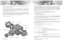
Gear Construction ZZ-Universal-Line® • ZZ-Precision-Line® The complete gear program is constructed as a modular system and by reusing parts, allows the assembly of different variations and combinations. The dimensions of the output shaft at ratio’s of i > 1 and all shaft arrangements, is constant. For ratio’s i < 1 (speed increase), the dimensions of the output shaft are different, due to the conditions of the construction. The input shaft (pinion shaft), has different dimensions, depending on the gear ratio, in the region of the flange and at the shaft ends. The output shaft can be chosen as...
Open the catalog to page 4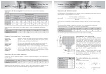
Designing a ZZ Bevel Gear Unit Operating Factors • Shock Load Factor Ambient Temperature Intermittent Operation • Additional Shaft Loading Single factor b3 for intermittent operation Single factor b1 for the operating mode of the prime mover and work machine, according to NIEMANN. The single factor b3 is used with intermittent operation. Factor b3 is dependent of the relative switch-on period, referred to an operating time of 60 minutes. Type of prime mover Shockload factor of work machine Designing a ZZ Bevel Gear Unit Turbine, hydraulic motor Single-cylinder piston Run-time per hour, under...
Open the catalog to page 5
Designing a ZZ Bevel Gear Unit Assembly - Shapes Additional Radial Loading on Input and Output Shafts Additional radial loading on the input shaft journals (d1) Gear unit size K080 Basically, the bevel gear units can be prepared for almost any mounting position. To comply with the assembly and lubrication conditions that depend on the mounting position, the necessary requirements with respect to accessibility, fixing side face, visible side of the oil supply elements must be specified according to the application. Various types are available, depending on the assembly shape. (Example: Assembly...
Open the catalog to page 6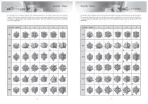
Assembly - Shapes As standard, the oil supply elements are located according to the type of gear and the mounting location. The assembly shapes illustrated here, for the more common applications, show the position of ventilation, oil gauge glass and drainage. Any deviation from the illustrations, will require a separate check and adaptation. Assembly - Shapes Assembly - Shapes As standard, the oil supply elements are located according to the type of gear and the mounting location. The assembly shapes illustrated here, for the more common applications, show the position of ventilation, oil gauge...
Open the catalog to page 7
values for torque, power and not integer output speeds (e.g. n1=50, i=3:1, n2=16,66, n2≈17) rounded P1 = input power , M2 = output torque bold print values: oil cooling recommended values for torque, power and not integer output speeds (e.g. n1=50, i=3:1, n2=16,66, n2≈17) rounded Drive (input) speed, n1 [rpm]] K140 Drive (input) speed, n1 [rpm] Drive (input) speed, n1 [rpm] Drive (input) speed, n1 [rpm] Power and Torque Ratings Power and Torque Ratings P1 = input power , M2 = output torque bold print values: oil cooling recommended
Open the catalog to page 8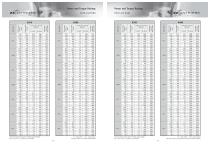
values for torque, power and not integer output speeds (e.g. n1=50, i=3:1, n2=16,66, n2≈17) rounded P1 = input power , M2 = output torque bold print values: oil cooling recommended values for torque, power and not integer output speeds (e.g. n1=50, i=3:1, n2=16,66, n2≈17) rounded K440 Drive (input) speed, n1 [rpm] K330 Drive (input) speed, n1 [rpm] Drive (input) speed, n1 [rpm] Drive (input) speed, n1 [rpm] Power and Torque Ratings Power and Torque Ratings P1 = input power , M2 = output torque bold print values: pressurised oil circulation system necessary
Open the catalog to page 9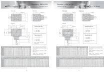
Standard-Type K Front view Standard-Type HK Front view Side view Thread M x t Side view Thread M x t Top view Standard type S L Not possible for types with hollow shafts Refer to page 18 for shaft dimensions. Gear size The oil supply holes are specified after mounting position and the gear fixings are known. Gear size Gear size Dimensions and illustrations without obligation; changes may be made without prior notice The oil supply holes are specified after mounting position and the gear fixings are known Shafts with centralised thread, according to DIN 332, Form D Spline dimensions, according to...
Open the catalog to page 10
Dimensions • K080 - K330 Ratio’s for high-speed Up to a gear ratio of i = 1:2, bevel gear units with shafts d1 (n1) can be fitted with a speed increasing ratio of d2 (n2). Because of the smaller bevel gear fitted to the output shaft, the diameter d2 of the shaft is also reduced. Therefore, the transferred torque and power is also reduced. The tables on pages 12-15 cannot be used for speed increasing ratio’s. Dimensions ZZ Bevel Gear Units with toe-plate mountings LK, with angle mountings, WK LK Front view Side view Thread M x t Possible special gear ratio’s L S: • i = 1:1,25 • i = 1:1,5 • i = 1:2,0...
Open the catalog to page 11All ZZ DRIVE TECH catalogs and technical brochures
 BEVEL GEAR UNITS ZZ-SERVOLINE
12 Pages

- Screw jack
- Servo-gearbox
- Index unit
- Rotary indexing table
- Cam indexer
- Metal screw jack
- Electric rotary indexing table
- Rotating screw jack
- Solid-shaft servo-gearbox
- Angle gearbox
- Horizontal rotary indexing table
- Motor-driven rotary indexing table
- Spiral gear
- Flange servo-gearbox
- Oscillating indexer
- Maintenance-free servo-gearbox
- Spiral bevel angle gearbox
- Flange angle gearbox
- Hypoid servo-gearbox