


- Company
- Products
- Catalogs
- News & Trends
- Exhibitions
Transmission Sphere Selection

Transmission Sphere Selection
A GPI or VeriFire interferometer is commonly used for examining spherical surfaces. This document provides guidance on selecting transmission spheres for testing these surfaces.
Transmission Spheres
Transmission spheres convert the collimated output beam of an interferometer into a spherical wavefront, serving as a beamsplitter. The quality of the reference wavefront depends on the master surface of the transmission sphere, which reflects a portion of the laser light back into the mainframe.
Lens Parameters
Transmission spheres are described using lens nomenclature, with the relative aperture or f/number (f/#) being a key parameter. The f/# indicates the steepness of the light cone at the lens focus, affecting the speed of the lens.
Surface Description
Surfaces are described using R/numbers (R/#), analogous to f/#, representing the radius of curvature divided by the clear aperture.
Measurement Scheme
Spherical surfaces are tested by aligning their center of curvature with the focus of the transmission sphere. Concave surfaces are tested in the diverging beam, while convex surfaces are tested in the converging beam.
Constraints
The f/# of the transmission sphere must match or exceed the R/# of the test surface for full coverage. If the f/# is slower, only partial coverage is achieved. A zoom feature can compensate for mismatches when the f/# is faster.
Standard Series
Transmission spheres are available in 4-inch and 6-inch diameters, with f/numbers ranging from f/0.75 to f/11. They offer flexibility for measuring both concave and convex surfaces.
Converger/Diverger Series
Diverging transmission spheres test mid-range concave surfaces, while converging spheres test mid-range convex surfaces. Each series covers specific radius ranges.
Practical Help
When selecting transmission spheres, consider the surfaces to be measured, their diameters, radii, and whether they are concave or convex. Use the provided worksheet to organize this information and choose appropriate transmission spheres.
Conclusion
ZYGO offers tools and support for selecting transmission spheres, including a free calculator tool. Contact ZYGO for assistance or to review completed worksheets.
Catalog excerpts

Transmission Sphere Selection Introduction A typical application for a GPI or VeriFire interferometer is the examination of spherical surfaces. A concave or convex spherical surface can be inspected for surface figure and irregularity by placing its center of curvature coincident with the focus of a transmission sphere. This Application Brief provides a basic understanding of transmission sphere selection for spherical surface testing. The f/1 lens is "faster" than the f/2. The relative aperture or f/# of a lens describes the steepness of the cone angle of the light at the focus of the lens. A narrow cone is conventionally referred to as from a "slow" lens while a broader cone is from a "fast" lens. This convention and nomenclature may be familiar since it is used for lenses of photographic cameras. What are Transmission Spheres? A transmission sphere is used to transform the collimated output beam of the interferometer mainframe into a spherical wavefront, and is used as a beamsplitter to divide the laser light into separate reference and measurement wavefronts. ZYGO transmission spheres are designed to snap into the accessory receptacle located on the interferometer mainframe, or an auxiliary receptacle remote from the mainframe, in the collimated output beam. The last surface of each transmission surface acts as the "master surface," commonly referred to as an aplanatic surface. The quality of the reference wavefront is dependent upon the figure quality of this master surface. The master surface reflects approximately 4 percent of the laser light back into the mainframe, to form the reference wavefront. The remaining laser light, in the form of a high quality spherical wavefront, acts as the measurement beam. As illustrated in Figure 1, this wavefront converges to a focus in front of the transmission sphere and then diverges on the other side of focus. The converging and diverging portions of the beam can be thought of as a library of precise spherical wavefronts with a limited range of converging radii and an infinite range of diverging radii. A number of different transmission spheres covering a range of f/numbers and apertures are required to accommodate the full range of convex and concave test possibilities. The reasons for this are explained in the following sections. Transmission Spheres of various apertures and f/numbers are available as standard accessories, and others may be obtained on special order. Describing the Surface Under Test Although it is a convention to describe a cone of light produced by a lens in terms of f/#, it is not conventional to describe the "speed" of a concave or convex surface in those terms. Instead, the convention is to use R/numbers. An R/number (R/#) is analogous to an f/#. It is the radius of curvature divided by the clear aperture of the spherical surface, as shown in Figure 3. Therefore f/# and R/#, if they are the same (e.g. f/2 and R/2), describe cones that have the same "speed." Measurement Scheme Figure 1 Transmission spheres are lenses, and as such are described using conventional lens nomenclature. One of the most significant parameters of a lens is its relative aperture, or speed. This is defined as the ratio of the focal length to the entrance pupil diameter (f/D) and is usually referred to as the f/number (f/#). A lens whose focal length is 8 inches (200 mm) and whose entrance pupil diameter (aperture) is 4 inches (100 mm) is referred to as an f/2 lens. Shown in Figure 2, an f/1 lens has a larger relative aperture (twice as large) and a higher speed than the f/2 lens shown in Figure 1. Spherical surface testing is accomplished by positioning the spherical surface to be tested in the beam with its center of curvature precisely at the focus of the transmission sphere. This has the effect of placing the test surface coincident with a spherical wavefront of identical radius. Concave surfaces are tested in the diverging portion of the beam (Figure 4), whereas convex surfaces are tested in the converging portion of the measurement beam (Figure 5). An interference pattern will result when the measurement wavefront, after reflecting back from the test surface, passes through the transmission sphere and into the interferometer where it interferes with the reference wavefront. 1|Page
Open the catalog to page 1
From this we can see that from a coverage point of view, only a few transmission spheres are necessary to cover a range of very fast to very slow surfaces. Some Constraints In order to measure an entire surface, the cone of light from the transmission sphere must be fast enough to completely fill (illuminate) the test surface. In other words, the f/# of the transmission sphere must be equal to or faster than the R/# of the test surface. If the f/# is slower than the R/#, only a portion of the surface will be tested (Figure 6). The ratio of R/# to f/# describes the percentage of the entire surface...
Open the catalog to page 2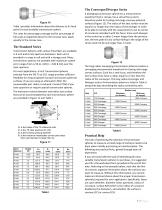
Table I provides information about the distance to its focal point for each available transmission sphere. The rules for percentage coverage and for percentage of full-scale as explained above for the concave case, apply equally to the convex case. A diverging transmission sphere has a measurement wavefront that is convex, has a virtual focus and is therefore useful for testing mid-range concave spherical surfaces (Figure 12). The radius of the test surface must be equal to or longer than the radius of the diverger in order to be able to comply with the requirement to set its center of curvature...
Open the catalog to page 3
In the following columns, select the transmission spheres that have an f/# that is equal to or faster (smaller) than the part R/#. This will assure full coverage of the surface. Enter the results as shown in the example and explained in the legend. Note that concave and convex surfaces can be measured with a range of transmission spheres, especially if you have the capability of the 6X zoom. The value of R1 for each transmission sphere is listed in each case to assist you in avoiding the radius limitations for convex testing. After you have completed the worksheet, a review of the results will...
Open the catalog to page 4All Zygo catalogs and technical brochures
 Zygo Nano Position Sensors
20 Pages
 Zygo Precision Optics & Systems
20 Pages
 Zygo Laser Interferometers
28 Pages
 Zygo 3D Optical Profilers
24 Pages
 Zygo Service Brochure
12 Pages
 Compass2 1-sheet - Optimized
2 Pages
 Compass 2™ Specifications
2 Pages
 Mx Surface Texture Parameters
28 Pages
 SubAngstrom Surface Texture
3 Pages
 PMI vs Fringe Analysis
2 Pages
 Mx Films Analysis Software
2 Pages
 Interferometer Scale Facton
2 Pages
 Coherent Artifact Reduction
3 Pages


- Automation software solution
- Microscope
- Windows software
- Optical microscope
- Industrial software
- Interface software
- Quality software
- Inspection microscope
- Glass lens element
- Spectrum lens element
- Optical window
- Surface measuring machine
- Optical lens element
- Compact microscope
- Visible lens element
- Digital microscope
- Metrology software
- Industrial surface measuring machine
- Instrument software
- Fluorescence microscope