 Website:
Zygo
Group: Ametek
Catalog excerpts

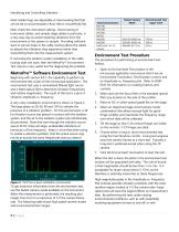
APPLICATION NOTE Identifying and Controlling Vibration For the best measurement performance on the NewView™ optical profilers, environmental vibrations must be minimized. These vibrations can be transmitted to the instrument itself, the test part, or both. ZYGO’s MetroPro™ software includes simple and useful tools for quantifying vibration. With these tools and a common sense approach, it is possible to identify sources of vibration and isolate them to produce the “quietest” measurement environment possible. How Does Vibration Affect the Data? Common Sources of Vibration Depending upon the sample surface, vibration effects can range from nearly undetectable to extremely visible and can be detrimental to data integrity. Figure 1 shows an SIC optical flat measured with 4 fringes of tilt. The image labeled A shows the orientation of the fringes on the camera. Image B shows the measured surface when a mechanical vibration is applied near the sample, and Image C shows a surface measured by the same non-vibrating system. While there are countless sources of problematic vibration, there is a small set that should be investigated first when vibration is encountered. Improperly installed or leveled isolation system Poorly routed or tightly stretched instrument cabling Proximity to air handling discharges or returns Proximity to mechanical pumps or other large machinery Acoustic coupling to the sample or fixture Figure 1 A. With vibration Vibrations stemming from these common sources are often quite large and sometimes can even be visually observed on the fringe monitor. If vibration of the fringe pattern is visible on the monitor, the following simple checks can help to eliminate them quickly. Basic Vibration Troubleshooting Figure 1 B. With Vibration Figure 1 C. Vibration Removed The first check should be the instrument isolation system. When installed and configured properly, an isolation system will effectively eliminate even very strong mechanical vibrations. The isolation system should be supplied with the recommended air pressure and all of the isolator legs should be floating—even one non-floating leg is enough to transmit vibrations to the interferometer. It is also important to ensure that the legs of the isolation system are properly
Open the catalog to page 1
Identifying and Controlling Vibration Most isolator legs are adjustable or have leveling feet that can be set to accommodate a floor that is not perfectly flat. Next, check the instrument cabling. Good routing of instrument cables, and sample stage cables in particular, is a very easy way to avoid imparting vibrations from the environment to the system or sample. Providing sufficient slack or service loops in the cable routing allows the cables to absorb the vibrations they experience rather than transmitting them into the measurement system. If correcting the isolation system installation...
Open the catalog to page 2
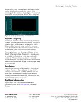
Identifying and Controlling Vibration airflow modifications, the environment test feature can be used to identify and isolate vibration sources. After correcting vibration problems, a typical good measurement environment will look similar to the plot shown in Figure 3. Figure 3. Typical “good” installation environment test Acoustic Coupling Occasionally, vibrations are not driven through mechanical coupling, but rather through acoustic coupling. This type of vibration source can be driven by sample design, fixture design, and tool locations, just to name a few examples. Using the MetroPro™...
Open the catalog to page 3All Zygo catalogs and technical brochures
-
Zygo Nano Position Sensors
20 Pages
-
Zygo Precision Optics & Systems
20 Pages
-
Zygo Laser Interferometers
28 Pages
-
Zygo 3D Optical Profilers
24 Pages
-
Zygo Service Brochure
12 Pages
-
Compass2 1-sheet - Optimized
2 Pages
-
Compass 2™ Specifications
2 Pages
-
Mx Surface Texture Parameters
28 Pages
-
SubAngstrom Surface Texture
3 Pages
-
PMI vs Fringe Analysis
2 Pages
-
Mx Films Analysis Software
2 Pages
-
Interferometer Scale Facton
2 Pages
-
Coherent Artifact Reduction
3 Pages


