 Website:
Zygo
Group: Ametek
Catalog excerpts

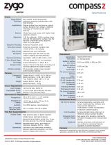
Specifications SYSTEM Measurement Technique Applications Scanner Objectives Objective Mounting Field Zoom Lenses Field of View Illuminator Measurement Array Z-Drive (Focus) Stage Part Stage Sample Holder Vibration Isolation Non-contact, three-dimensional, coherence scanning interferometry with field stitching Optical surface form and texture; optical surface deviation from design; relational metrology of mechanical and datum features Closed-loop piezo-based, with highly linear capacitive sensors 2.5X for relational / 20X for surface (typ); 10X and 50X optional for surface; See the Nexview & NewView Series Objective Chart for more details Motorized 4-position turret Motorized 3-position encoded zoom • 0.5X, 0.75X, 1.5X included Objective and zoom selectable Single white-light LED with long life, uniform imaging and high efficiency Selectable: 1408 x 1408, 1024 x 1024 100 mm range with 0.1 µm resolution 5-axis containing X, Y, Pitch, B, C, Vacuum Chuck for flat base pin tooling and Universal adhesive lens holder included 3D pneumatic isolation legs included Active solution optional PHYSICAL Dimensions (HWD) Weight System & encl: ~160 x 116 x 106 cm Electronics Rack: ~138 x 61 x 96 cm Typ. Footprint (WD): 185 x 172 cm System & Encl: 820 kg Electronics Rack: 76 kg UTILITY REQUIREMENTS Input Voltage Compressed Air for Table 100 to 240 VAC, 50/60 Hz 4.1 to 5.5 bar (60 to 80 psi); dry and filtered; 6 mm OD hose input ENVIRONMENTAL REQUIREMENTS Temperature Temperature Change Humidity Floor / Acoustic Vibration limits 20 to 23°C with +/- 0.1°C stability *required for performance to specification <0.2°C per hr and <1°C per 24 hr *maximum allowed thermal change Specification Description Aspheric Surface Roughness Lens Height Tilt Control Interlock Flatness Lens Concentricity to Interlock Interlock Diameter Tilt Control Interlock Parallelism Tilt Control Interlock Thickness MEASUREMENT MODES 3D Form & Texture High-precision glass or plastic injection molded lenses and optical devices, diamond-turned molds. with a CA < 8 mm Form Deviation Production Form Deviation Mode for form and CA < 6.4 mm for relational Material Geometries Uncoated metal, glass, and plastic w/ reflectivity between 0.05% - 100% Continuous and rotationally symmetric spheres, gullwings, pancakes, and other asphere shapes plus freeforms Specifications subject to change without prior notice. SS-0134 08/22 © 2022 Zygo Corporation. All rights reserved. Target performance 1 reproducibility Aspheric Surface Form Error TEST PART CHARACTERISTICS Sample Types Full area topography, waviness, and texture (tooling marks, artifacts, etc.) measurement defined by: ● OpticStudio & CODE V prescription ● Unknown surface tracking Full area deviation map when lens is measured using a surface equation Ring-spoke form deviation method for increased throughput with reduced data density Flatness, thickness, and centration of lens surface to mechanical datums. Capability is surface dependent FOOTNOTE Performance specifications under laboratory conditions using standard specimens, according to ISO 25178-601, 25178-604 and 5436-1. ZYGO CORPORATION LAUREL BROOK ROAD • MIDDLEFIELD, CT 06455 VOICE: 86
Open the catalog to page 1
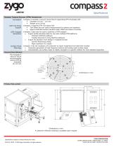
Specifications DIAMOND TURNING MACHINE (DTM) INTEGRATION Jig Support DTM Tool Setup Support DTM Toolpath Generation Surface Finish Metrology Compass 2 includes a vacuum chuck fixture supporting DTM chuck/jigs with Diameter 16 mm – 115 mm Weight up to 0.8 kg Compass 2 supports DTM Tool setup with Tool offset and tool radius measurement for spheres and aspheres Report predicted surface deviation after offset and radius correction Compass 2 data may be used to optimize a DTM toolpath Export profile deviation data for use with multiple DTM platforms o Precitech DIFFSYS software o...
Open the catalog to page 2All Zygo catalogs and technical brochures
-
Zygo Nano Position Sensors
20 Pages
-
Zygo Precision Optics & Systems
20 Pages
-
Zygo Laser Interferometers
28 Pages
-
Zygo 3D Optical Profilers
24 Pages
-
Zygo Service Brochure
12 Pages
-
Compass2 1-sheet - Optimized
2 Pages
-
Mx Surface Texture Parameters
28 Pages
-
SubAngstrom Surface Texture
3 Pages
-
PMI vs Fringe Analysis
2 Pages
-
Mx Films Analysis Software
2 Pages
-
Interferometer Scale Facton
2 Pages
-
Coherent Artifact Reduction
3 Pages


