- Company
- Products
- Catalogs
- News & Trends
- Exhibitions
MH-Z14B
1 /8Pages

MH-Z14B
1 /8Pages
Catalog excerpts

Infrared Carbon Dioxide Module (Model: MH-Z14B) User’s Manual V1.1 Valid from June 18th,2021 Zhengzhou Winsen Electronics Technology CO., LTD.
Open the catalog to page 1
Statement The copyright of this manual belongs to Zhengzhou Winsen Electronics Technology Co., LTD. Without the written permission, any part of this manual shall not be copied, translated, stored in database or retrieval system, also can’t spread through electronic, copying, record ways. Thanks for purchasing our product. In order to enable customers to better use the product and reduce the faults caused by misuse, please read the manual carefully and operate it correctly in accordance with the instructions. If users disobey the terms or remove, disassemble, change the components inside of the...
Open the catalog to page 2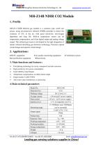
Zhengzhou Winsen Electronics Technology Co., Ltd MH-Z14B NDIR CO2 Module 1. Profile MH-Z14 NDIR Infrared gas module is a common type, small size sensor, using non-dispersive infrared (NDIR) principle to detect the existence of CO2 in the air, with good selectivity, non-oxygen dependent and long life. Built-in temperature sensor can do temperature compensation; and it has digital output and analog voltage output. This infrared gas sensor is developed by the tight integration of mature infrared absorbing gas detection technology, Precision optical circuit design and superior circuit design. 2....
Open the catalog to page 3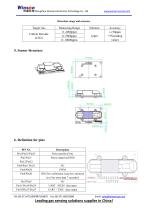
Zhengzhou Winsen Electronics Technology Co., Ltd Detection range and accuracy Target Gas Carbon Dioxide (CO2) Power positive(Vin) Power negative(GND) HD (Zero calibration, keep low electrical level for more than 7 seconds)) UART(RXD)data input UART(TXD)data output Email: [email protected] Leading gas sensing solutions supplier in
Open the catalog to page 4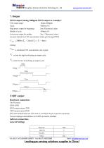
Zhengzhou Winsen Electronics Technology Co., Ltd 7. Output PWM output (taking 2000ppm PWM output as example): CO2 output range: 0ppm-2000ppm Cycle: 1004ms±5% High power output for beginning: 2ms (Theoretical value) Middle of cycle: 1000ms±5% Low power output for ending: 2ms(Theoretical value) Account formula for CO2 concentration which gets through PWM: is calculated CO2 concentration, unit is ppm; TH is time for high level during an output cycle; TL is time for low level during an output cycle. UART output Hardware connection: Vin-5V power GND- GND RXD connect sensor TXD TXD connect sensor RXD...
Open the catalog to page 5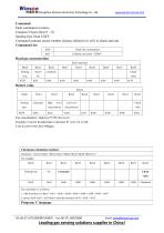
Zhengzhou Winsen Electronics Technology Co., Ltd Command Each command or return: Contains 9 bytes (byte 0 ~ 8) Starting byte fixed 0 XFF Command contains sensor number (factory default to 0 x01) to check and end Command List: 0x86 Calibrate zero point(ZERO) Read gas concentration Send command Byte0 Return value Return Byte0 Gas concentration= high level *256+low level Example: Convert hexadecimal to decimal: 01 is 01, F4 is 244; CO2 level:01*256+244=500ppm Checksum calculation method Checksum = (Invert (Byte1+Byte2+Byte3+Byte4+Byte5+Byte6+Byte7))+1 For example: Byte0 Starting byte Check value...
Open the catalog to page 6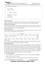
Zhengzhou Winsen Electronics Technology Co., Ltd char get CheckSum (char *packet) { char i, checksum; for ( i = 1; i < 8; i++) { checksum += packet[i]; } checksum = 0xff – checksum; checksum += 1; return checksum; } Zero Point Calibration: In order to facilitate the user to calibrate the zero point, the sensor has two zero calibration methods: manual zero calibration and command zero calibration. The zero point calibration function refers to calibrating 400ppm. ①Manual zero point calibration Manual zero point calibration is to input low level (0V) to the HD pin of the sensor to calibrate zero...
Open the catalog to page 7
Zhengzhou Winsen Electronics Technology Co., Ltd diffusion windows should be in a well-ventilated position. The sensor should be far away from heat sources and avoid direct sunlight or other heat radiation. The sensor should be calibrated regularly, and the calibration period is recommended to be no more than 6 months. Do not use the sensor for a long time in an environment with high dust density. In order to ensure that the sensor can work normally, the power supply voltage must be maintained in the range of (5.0±0.1)V DC, and the power supply current must not be less than 150mA. If it is...
Open the catalog to page 8All Zhengzhou Winsen Electronics Technology Co., Ltd catalogs and technical brochures
 ME4-NO2
6 Pages
 ME4-H2S
6 Pages
 ME4-SO2
6 Pages
 ME4-ETO
6 Pages
 ZE11
ZE117 Pages
 ZE12A
ZE12A5 Pages
 MQ136
MQ1366 Pages
 MQ137
MQ1376 Pages
 ME3-HCL
5 Pages
 UE-NH3
4 Pages
 MEu-H2S
6 Pages
 ME3-C2H3Cl
4 Pages
 ME3-C8H8
5 Pages
 ME3-CH4S
5 Pages
 ME3-C2H6S
5 Pages
 ME3-C2H6S2
5 Pages
 ME3-C3H9N
5 Pages
 ME3-CS2
5 Pages
 ZE801-NH3
4 Pages
 ZE802-C3H9N
4 Pages
 ZE803-H2S
5 Pages
 ZE804-CH4S
4 Pages
 ZE805-C2H6S
4 Pages
 ZE806-C2H6S2
4 Pages
 ZE807
ZE8074 Pages
 ZE808
ZE8084 Pages
 ZE809
ZE8094 Pages
 GM-202B
7 Pages
 GM-402B
8 Pages
 MP-2
MP-26 Pages
 MP-4
MP-47 Pages
 MP-4C
MP-4C7 Pages
 MP-5
MP-57 Pages
 MQ-2
MQ-27 Pages
 MQ-2B
MQ-2B7 Pages
 MC101
MC1016 Pages
 MC105
MC1056 Pages
 MC107
MC1076 Pages
 MC227D
6 Pages
 MC101B
6 Pages
 MC106
MC1066 Pages
 MC106B
6 Pages
 MC107B
6 Pages
 MC226A
6 Pages
 MC112/MC112C/MC112D
7 Pages
 MC113
MC1136 Pages
 MC114/MC114C
6 Pages
 MC115
MC1156 Pages
 MC109
MC1096 Pages
 MC119
MC1196 Pages
 MH-440D
6 Pages
 MH-441D
7 Pages
 ZP04
ZP047 Pages
 ZP13
ZP135 Pages
 ZP14
ZP148 Pages
 ZC05
ZC057 Pages
 ZC08
ZC086 Pages
 ZC13
ZC137 Pages
 MQ-4
MQ-47 Pages
 MQ-4B
MQ-4B7 Pages
 MQ-5
MQ-57 Pages
 MQ-5B
MQ-5B7 Pages
 MQ-6
MQ-67 Pages
 MD61
MD616 Pages
 MR513
MR5137 Pages
 ZP10
ZP105 Pages
 ZP06
ZP065 Pages
 ZP05
ZP055 Pages
 ZC02
ZC025 Pages
 ZC01
ZC015 Pages
 MR007
MR0076 Pages
 MPn-4C
7 Pages
 MH-T7042A
7 Pages
 MH-L1141A-U-100L
7 Pages
 MC21B
MC21B6 Pages
 MH-T4041A
6 Pages
 ZPH01B
10 Pages
 ZPH01
ZPH018 Pages
 ZPH02
ZPH029 Pages
 ZPH03
ZPH039 Pages
 ZPH04B
10 Pages
 ZH06-Ⅰ
12 Pages
 ZH06-II
11 Pages
 ZH06-III
13 Pages
 ZH06-IV
14 Pages
 ZH08
ZH086 Pages
 ZH09
ZH0914 Pages
 ZPH05
ZPH057 Pages
 ME2-O2-Ф20
4 Pages
 US1000
8 Pages
 MEu-O2
5 Pages
 MEu-2O2
5 Pages
 MED-O2-LA
5 Pages
 US1010
8 Pages
 ME2-O3
6 Pages
 ME2-O3-16x15
6 Pages
 ME3-O3
5 Pages
 MQ131-H
7 Pages
 MQ131-L
7 Pages
 ZQ02-O3
7 Pages
 ZE25A-O3
7 Pages
 GM-512B
7 Pages
 MP901
MP9017 Pages
 MP135
MP1357 Pages
 MQ138
MQ1386 Pages
 MQ316
MQ3166 Pages
 WSP2110
7 Pages
 MQ135
MQ1357 Pages
 ZP01-MP503
5 Pages
 ZM01
ZM019 Pages
 ZE40B-TVOC
6 Pages
 4R-PID
6 Pages
 ZP101
ZP1016 Pages
 ZP16
ZP166 Pages
 ZP16-A
5 Pages
 ME2-CH2O-Ф16
5 Pages
 ME2-CH2O-16×15
6 Pages
 ZE07-CH2O
6 Pages
 ME3-CH2O
5 Pages
 ZE510-CH2O
8 Pages
 ZE08B-CH2O
6 Pages
 ME3-H2
5 Pages
 ME4-H2
6 Pages
 ZE07-H2
6 Pages
 ZE21-H2
5 Pages
 ZC08-H2
6 Pages
 MQ-8
MQ-87 Pages
 CMV-2021D
7 Pages
 GMV-2021B
8 Pages
 ZC61
ZC617 Pages
 MEv-GH01
6 Pages
 MPv-820
7 Pages
 ZE610-H2
6 Pages
 MP810
MP8107 Pages
 MC33J
MC33J6 Pages
 GM-702B
7 Pages
 MP-7
MP-76 Pages
 MP-9
MP-96 Pages
 ME2-CO-Ф14x14
5 Pages
 ME2-CO
5 Pages
 ME2-CO-Ф14x50-C
4 Pages
 ME3-CO
5 Pages
 ME4-CO-E4
5 Pages
 ME4-CO
6 Pages
 ZE03G
ZE03G7 Pages
 ZE03
ZE037 Pages
 ZE07-CO
6 Pages
 ZE15-CO
6 Pages
 ZE16B-CO
5 Pages
 ZE16-CO
5 Pages
 ZE18-CO
5 Pages
 MQ-9B
MQ-9B7 Pages
 MQ-7B
MQ-7B7 Pages
 ME2-CO-Φ14x5
6 Pages
 MEu-2CO
6 Pages
 ZE730-CO
6 Pages
 MEu-CO
6 Pages
 MEs-CO
6 Pages
 MH-Z14A
10 Pages
 MH-Z19D
6 Pages
 MH-411D
6 Pages
 MH-712B
6 Pages
 MG-812
6 Pages
 MD62
MD627 Pages
 MH-711A
9 Pages
 MH-410D
6 Pages
 MH-Z16
5 Pages
 MH-Z1311A
5 Pages
 GM-502B
7 Pages
 MP503
MP5037 Pages
 MP801
MP8016 Pages
 MP905
MP9056 Pages
 MH-Z19C
8 Pages
 MH-Z19E
6 Pages
 MH-Z1911A
6 Pages
 ZP07
ZP075 Pages
 ZE08-CH2O
7 Pages
 ZE14-O3
5 Pages
 ZE25-O3
6 Pages
 ZE27-O3
7 Pages
 WHT20
WHT2017 Pages
 ZS03
ZS038 Pages
 ZS05
ZS058 Pages
 MS-Z3
MS-Z36 Pages
 ZPH04
ZPH0410 Pages
 ZH03B
ZH03B11 Pages
 ZH07
ZH0712 Pages
 ZS21
ZS2111 Pages
 ZH10-F
10 Pages
 ZE08K-CH2O
8 Pages
 ZE40-TVOC
6 Pages
 ZM106-VOC
8 Pages
 ZPHS01
7 Pages
 ZEHS04
8 Pages
 ZCE04B
6 Pages
 ZPHS01B
7 Pages
 ZPHS01C
9 Pages
 ZH10-VHT
11 Pages
 ZPS20
ZPS208 Pages
 Winsen Flame Sensors
1 Page
 Winsen Hydrogen H2 Sensor
2 Pages
 Winsen Water Quality Sensors
2 Pages
 Winsen Gas Flow Sensors
2 Pages
 Winsen Product Catalog-Complete
22 Pages
 Winsen Pressure sensor
2 Pages


- Resistance temperature sensor
- Pressure transmitter
- Analog pressure transmitter
- Acceleration sensor
- Pressure probe
- Gas detector
- Waterproof pressure transmitter
- Membrane pressure transmitter
- Stainless steel pressure transmitter
- Piezoelectric accelerometer
- Digital pressure transmitter
- Humidity and temperature probe
- Level transmitter
- Gas pressure transmitter
- Industrial detector
- Liquid level transmitter
- Liquid pressure transmitter
- Relative humidity and temperature sensor