- Catalogs
- Zhejiang Huiren Electronics Co. Ltd.
- SINGLE-PHASE INVERTER / THREE-PHASE / FREQUENCY / IGBT-SG200 SERIES
- Company
- Products
- Catalogs
- News & Trends
- Exhibitions
SINGLE-PHASE INVERTER / THREE-PHASE / FREQUENCY / IGBT-SG200 SERIES
1 /82Pages

SINGLE-PHASE INVERTER / THREE-PHASE / FREQUENCY / IGBT-SG200 SERIES
1 /82Pages
Catalog excerpts

Preface This manual can provide you with the detailed rules and precautions, including installation, wiring, the setting of functional parameter, daily maintenance, malfunction diagnosis and solution etc. To give full play to its function and ensure the safety of both users and product, please read this manual carefully before using it. Any incorrect operations may lead to fault, malfunction or shortened lifetime, even damage of device and accident casualty. Please pay attention to the following points when using it: Power must be shut off before wiring Ground wire must be connected correctly In any case, AC power lines can't be connected to the output terminals, such as U, V or W Do not touch the internal components for safety Only the qualified electronic engineer is allowed to assemble, wire, repair or maintain the converter Converter must be installed in a appropriate operating environment and far away from humidity or water drops; care must be taken to prevent it from direct sunlight or being overheated Do not conduct the procedure of inspection or maintenance until converter has been shut down for more than 3 minutes No permission is granted to change or modify the internal components or circuits. Do not conduct the Withstand Voltage Test on the internal components This product can't be applied in the situation that may endanger personal safety This manual is enclosed randomly as an attachment, please keep it safe in case that you need it for the inspection or maintenance of this product. Any information in this manual is subject to change without notice in accordance with our policy of continuous improv
Open the catalog to page 1
Acceptance 1.1 Inspection on Delivery 1.2 Illustrations for Nameplate INSTALLATION 2.1 Installation Environment 2.2 Installation Instructions and Space Limit WIRING 3.1 Connection Methods for Assorted Devices 3.2 Standard Wiring Diagram 3.3 Descriptions of Major Loop's Terminal 3.4 Illustrations for Control Loop's Terminal Keyboard and Panel 4.1 Illustrations of Keyboard 4.2 Operating Instructions RUNNING 5.1 Commissioning 5.2 Quick debugging Specification of Functional Parameters 6.1 Functional Parameters Table 6.2 Detailed of function parameters Fault Correcting 7.1 Malfunction and Solutions...
Open the catalog to page 2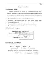
1-1 Inspection on Delivery Pre-delivery inspection for each converter will be implemented strictly by our QC Department; meanwhile, the packaging will be strengthened with special packing materials which can protect it from damage caused by collision. Please find the following points to check after unpacking it: • Please check if there is any damage caused during the transportation; • Please check if the enclosed documents are all inside the case, including manual, certificate and warranty card • Please check if this is the model of the product for which you placed an order • Please check whether...
Open the catalog to page 3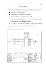
Chapter 3 Wiring (For the safety of operator as well as devices, only the qualified electronic engineer is allowed to operate it. Please pay attention to the following precautions while wiring:) Power must be shut off before wiring PE earth terminal must be connected with the ground The rated voltage must be in conformity with AC voltage Power cords must be connected with the terminal R, S and T while lines for motor should be connected with terminal U,V and W; any incorrect connection may cause damage to the internal components of converter The reliability of the terminals and wires must be...
Open the catalog to page 5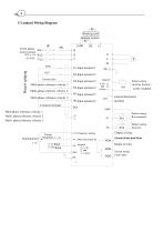
4 3-2 andard Wiring Diagram BR 制动单元 Braking unit Three-phase 三相电源 R/L1 power source Default setting External fault 外部故障 Multi-phase reference velocity 1 多步速一 定 Multi-phase多步速二 velocity 2 reference Multi-phase reference velocity 3 多步速三 公共端子 Common terminal Multi-phase reference velocity 1 Multi- phase reference velocity 2 Multi- phase reference velocity 3 external Keyboard 外引键盘接口 interface setting 频率设定用电源 Default setting: 出厂设定:方向指示 Direction Default setting: 出厂设定:运行指示 Run command
Open the catalog to page 6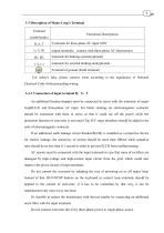
3-3 Description of Major Loop's Terminal For safety's sake, please connect wires according to the regulations of National Electrical Code while proceeding wiring 3-3-1 Connection of input terminal R, S, T An additional breaker/chopper must be connected in series with the terminals of major loop(R,S,T) and three-phase AC input. For better running, an electromagnetic contactor should be connected with them in series so that it could cut off the power while the protection function of converter is activated (Tip: R-C surge absorbers should be added to the ends of electromagnetic contactor. If an...
Open the catalog to page 7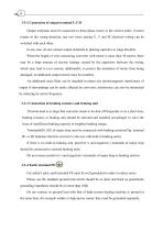
6 3-3-2 Connection of output terminal U,V,W Output terminals must be connected to three-phase motor in the correct order; if motor rotates in the wrong direction, any two wires among U, V and W electrical wiring can be switched with each other. In any case, do not connect output terminals to phasing capacitor or surge absorber. When the length of wire connecting converter with motor is more than 50 meters, there may be a large amount of electric leakage caused by the capacitors between the wiring, which may lead to over current; additionally, to protect the insulation of motor from being damaged,...
Open the catalog to page 8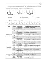
All the converters must be connected to the same earth terminal directly if two or more converters are installed together; please refer to the wiring layout below: 3-4 Explanations of control loop terminals
Open the catalog to page 9
Multi-core shielded cable or stranded wire should be used to connect and control terminals. The terminal which is closed to converter must be connected to earth terminal PE while shielded cable is applied to it. When wiring, control cable must be kept away from main circuit and high-current circuit at least 20cm, such as power lines, motor wires, wires for contactor and relay. Instead of parallel wiring, vertical wiring should be adopted to prevent converter from malfunction resulted from external interference.
Open the catalog to page 10
Chapter 4 Keyboard & Panel4-1 Illustrations of Keyboard4-1-1 Diagram of Keyboard Li nil ind-.calD' light And reversing Icma-Th« i-j’ii il: iwwhi Lglils wenl sul: forward potentiometer The shift key External term no I control indicator LlreLlivu’ an i Invalid Display the Infnrmjrtinn and 1h« rcl jrn key Increasing the key Programming key 4-1-2 Indicator light show 1) Functional indicator light: Light is the name of the
Open the catalog to page 11All Zhejiang Huiren Electronics Co. Ltd. catalogs and technical brochures


- Control pedal
- Displacement transducer
- Single pedal pedal
- Electronic pedal
- Linear displacement sensor
- Analog displacement transducer
- Solar DC/AC inverter
- Hall effect joystick
- Industrial displacement sensor
- Precision displacement sensor
- Three-phase DC/AC inverter
- Single-axis joystick
- Joystick with buttons
- Analog joystick
- 2-axis joystick
- Remote control joystick
- IP65 joystick
- Rugged joystick
- Single-phase DC/AC inverter
- Joystick for medical applications