
- Catalogs
- ZF Friedrichshafen AG
- OPERATING INSTRUCTIONS


- Company
- Products
- Catalogs
- News & Trends
- Exhibitions
OPERATING INSTRUCTIONS

OPERATING INSTRUCTIONS
This document provides operating instructions for the ZF-Duoplan two-speed gearbox models 2K450 and 2K600, aimed at specialists in maintenance and repair. It emphasizes compliance with safety regulations to prevent injury and damage.
Key safety instructions include ensuring personal safety during repairs, compliance with legal safety requirements, and proper training for repair staff. Environmental hazards are highlighted, particularly the proper disposal of lubricants and cleaning products.
The ZF-Duoplan gearbox is used in machine tool drives, suitable for torque increase or speed reduction. It features a compact planetary design, high efficiency, and low-noise operation. The gearbox is flange-mountable to various motors and allows for high radial forces on the output end.
The 2K450 model has a nominal power of up to 47 kW and the 2K600 up to 63 kW, both with a nominal speed of 1000 rpm. Detailed specifications include input and output torque, weight, and installation positions.
Instructions cover axial and radial runout tolerances for the drive motor, emphasizing the importance of maintaining specified tolerances for fault-free operation. Balancing types for the motor and gearbox are also discussed.
Maintenance procedures include regular oil changes and inspections. A fault checklist is provided for troubleshooting, along with detailed disassembly instructions.
This section addresses common queries related to the operation and maintenance of the gearbox, providing additional guidance for users.
When ordering motors, it is crucial to specify motor data, dimensions, and balancing type. Motor output shafts come with standard fitted keys according to EN 50347: 2001.
- Semi-key Balancing: Involves filling the keyway with a balance compensation equivalent to half a key. Rebalancing is recommended after assembly.
- Full-key Balancing: The motor shaft is balanced with a full key, and the hub is not.
Motors must have a flange-mounting option for gearboxes. Different gearbox variants are used based on motor type, with specific reference dimensions for hub position.
- Open Design: Gearbox without adapter plate but with a seal on the motor output shaft.
- Closed Design with Hub Bearing: Includes a ball bearing to prevent axial hub migration.
- Closed Version with Shaft Seal: Features an adapter plate with a shaft seal.
- Open Design with Adapter Ring: Allows adaptation to different connection dimensions.
- Version with Pulley Drive: The pulley is centered on the drive flange and must be balanced.
The M8 set screw must be tightened with 18 Nm, and the O-ring must be correctly positioned and greased. The gearbox is bolted to the motor using hexagon bolts, filled with oil, and connected to the lubrication system.
- Belt Output: The belt pulley must be centered and balanced.
- Coaxial Output: Delivered with full-key balancing.
- Without Output: The output shaft is manufactured by the customer.
The gearbox is connected using an 8-pole Harting connector. The shift unit requires a 24 V DC supply. Gear changes are controlled by applying voltage to specific pins, with the polarity determining the engaged gear.
The document outlines procedures for operating and maintaining the 2K450/2K600 gearbox, including instructions for reducing the main spindle motor speed and changing gear ratios.
The gearbox uses splash lubrication for intermittent operation and recirculating lubrication for continuous operation. The oil level must be maintained at the middle of the oil sight glass.
Before operation, ensure correct installation, including mechanical fastening, motor flange-mounting, and electrical connections.
Oil changes are required every 5000 operating hours. Used oil must be disposed of according to environmental protection laws.
Repairs should be conducted by authorized personnel. A checklist is provided for diagnosing gearbox faults.
The FAQ section addresses common issues such as loud gearbox noises and leaking.
The document includes diagrams showing oil inlet and outlet points and tables detailing ports and connections for lubrication.
Catalog excerpts

ZF-Duoplan Two-speed Gearbox 2K450 / 2K600
Open the catalog to page 1
This document is protected by copyright. Complete or partial reproduction or dissemination of this document is prohibited without the consent of ZF Friedrichshafen AG. Infringements lead to civil and criminal prosecution. This document is a translation of the German original.
Open the catalog to page 2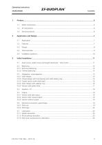
ZF-DUOPLAN Contents
Open the catalog to page 3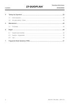
ZF-DUOPLAN Operating Instructions 2K450/2K600
Open the catalog to page 4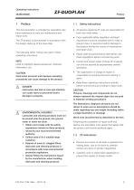
ZF-DUOPLAN Preface 1 Preface This documentation is intended for specialists who have experience to carry out maintenance and repair work. The ZF product is documented in accordance with the design status as of the issue date. The following safety notices are used in these operating instructions: Used to highlight special sequences, methods, information, etc. Used when incorrect and improper operating procedures can cause damage to the product. Used when due lack of care and attention can cause injury to personnel and/or damage to property. Lubricants and cleaning products must not be poured onto...
Open the catalog to page 5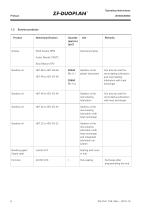
ZF-DUOPLAN Operating Instructions 2K450/2K600 1.3 Service products Product
Open the catalog to page 6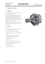
ZF-DUOPLAN Application and Design 2 Application and Design 2.1 Application The ZF-DUOPLAN two-speed gearbox is mainly used in machine tool drives. By way of example, the gearbox can be used in turning machines (horizontal B5) or machining centers (vertical V1) thanks to its variable installation position. The gearbox is also suitable for use in many systems in which torque increase or speed reduction is required. The gearboxes have coaxial output and are suitable for the high speeds generated in machine tool construction. • Two-speed gearboxes for AC and DC main spindle drives in machine tools...
Open the catalog to page 7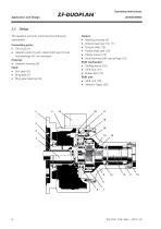
ZF-DUOPLAN Operating Instructions 2K450/2K600 2.3 Design The gearbox primarily comprises the following assemblies: Connecting parts: • Adapter plate (2) with radial shaft seal (3) and hub bearings (4), as necessary • Ring gear bearings (8) • Radial shaft seal (13) • Axial bearing with cup springs (15) Shift mechanism: Shift unit:
Open the catalog to page 8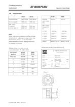
ZF-DUOPLAN Application and Design When using engine brakes/counterflow to brake the spindles (e. g. emergency stop) ensure that the moments of inertia do not exceed the admissible output torques. Braking times must be adapted accordingly. Standard fixing dimension (in mm) in accordance with EN 50347: 2001 Model plate (affixed to gearbox housing) TYPE _ PARTS LIST___ BACKLASH INPUT TURN _ RPM
Open the catalog to page 9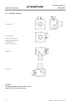
Operating Instructions Application and Design Installation positions Horizontal B5 Shift unit on right side, gearbox turned around longitudinal axis (view to output end) CAUTION The breather outlet must always be at the top, regardless of the installation position.
Open the catalog to page 10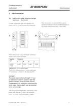
ZF-DUOPLAN Initial Installation 3 Initial Installation3.1 Axial runout, radial runout and length tolerances - drive motor In order to guarantee fault-free operation, the motor must not exceed the specified tolerances. Take into account the motor shaft elongation caused by heating in motors with fixed bearing on the B-side (opposite the motor output shaft). Axial runout, radial runout and length tolerances -electric motor mounting flange: Please note that the tolerance of the shaft length “L" is restricted in relation to the DIN standard The special tolerance for shaft length "L" must be maintained...
Open the catalog to page 11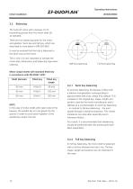
Initial Installation ZF-DUOPLAN Operating Instructions 2K450/2K600 3.2 Balancing The hubs (2) come with a keyway (1) for transmitting power from the motor shaft (3) as standard. There are two balancing types for the motor and gearbox: Semi-key and full-key, which are described in more detail in DIN ISO 8821. It must be ensured that the hub is balanced in the same way as the motor. This is why it is very important to indicate the motor data, dimensions and balancing type when ordering. Motor output shafts with standard fitted key in accordance with EN 50347: 2001 Shaft diameter In the case of...
Open the catalog to page 12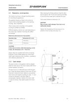
ZF-DUOPLAN Initial Installation 3.3 Adaptation, motor/gearbox The motors must have a flange-mounting option for mounting the gearboxes. The gearbox housing is fitted to the motor by means of the centering adapter on the bearing housing. This is standard. There is also a foot mounting on the gearbox housing for 2K450 and 2K600. Different gearbox variants are used depending on the motor type. Gearbox mounting also differs accordingly. Reference dimensions for hub position After cleaning the fitting surfaces, heat the drive hub to approx 120 °C from the opening and slide it onto the motor shaft...
Open the catalog to page 13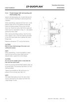
Operating Instructions Initial Installation Closed design with hub bearing and shaft sealing ring Variant with ball bearing (4), in which the hub (1) is also mounted in bearings to prevent axial hub migration. When assembling, separate the drive hub (1) with adapter plate (5) from the gearbox housing (6). Clean the fitting surfaces of the motor (3) and drive hub. Check the motor shaft (2) for axial and radial runout as described in chap. 3.1. Also lightly grease the motor shaft. After cleaning the fitting surfaces, heat the drive hub to approx 120 °C from the opening and slide it onto the motor...
Open the catalog to page 14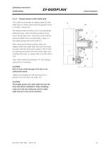
Initial Installation Closed version (with shaft seal) This variant incorporates an adapter plate (5) with shaft seal (7), which means that the gearbox forms a compact, closed unit. The adapter plate and drive hub (1) are separately delivered loose. Clean the fitting surfaces of the motor (3) and drive hub. Check the motor shaft for axial and radial runout as described in chap. 3.1. Also lightly grease the motor shaft (2). After cleaning the fitting surfaces, place the adapter plate with radial shaft seal onto the motor housing. Heat the drive hub to approx 120 °C from the opening and slide it...
Open the catalog to page 15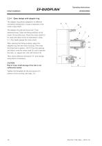
Operating Instructions Initial Installation Open design with adapter ring The adapter ring allows adaptation to different connection dimensions. A seal is required on the motor output shaft. The adapter ring (5) and drive hub (1) are delivered loose. Clean the fitting surfaces of the motor (3) and drive hub. Check the motor shaft (2) for axial and radial runout as described in chap. 3.1. Also lightly grease the motor shaft. After cleaning the fitting surfaces, place the adapter ring onto the motor housing. Then heat the drive hub to approx. 120 °C from the opening and slide it onto the motor...
Open the catalog to page 16All ZF Friedrichshafen AG catalogs and technical brochures
 ZF Duoplan 2K
40 Pages
 ZF-Single-disc
20 Pages
 ZF-Tiratron
24 Pages
Archived catalogs
 Innovations of Great Value.
9 Pages
 ZF-Servoplan PG
16 Pages
 Moving the big things
13 Pages
 ZF Eco liFE Rail
2 Pages
 Experiencing Dynamics - reliably
15 Pages
 TraXon at a Glance
2 Pages
 Suspension Springs for PC
886 Pages
 ZF MIXES the world
4 Pages
 ZF IS EFFICIENCY
23 Pages
 CV Chassis Modules
8 Pages
 Swing gearboxes GFB
16 Pages
 Gearboxes for winches GPT-W
5 Pages
 ZF. Network of Competence
8 Pages
 DMU Driveline System
2 Pages
 Drive gearboxes GPT/GFA
24 Pages
 GEARBOXES FOR WINCHES
16 Pages
 ZF Swing Gearboxes
16 Pages
 ZF Drive Gearboxes
24 Pages
 Bow Thruster
4 Pages
 Windenergy Image
4 Pages
 T-7000 tractor transaxle
2 Pages


- Planetary gearbox
- Coaxial gearhead
- Precision gearhead
- Hollow-shaft gearhead
- Multi-stage gearhead
- Machines gearbox
- Dual-stage gearbox
- Low-backlash gearhead
- High-efficiency gearhead
- High-torque gearhead
- High-precision gearhead
- Maintenance-free gear reducer
- Machine tool gear reducer
- Machine gear reducer
- Shaft-mounted gear reducer
- Mounted gear reducer
- Clutch and brake
- Universal gear reducer
- Vertical gear reducer
- Combined clutch-brake unit