- Catalogs
- ZF Friedrichshafen AG
- Damping Systems for Rolling Stock
- Company
- Products
- Catalogs
- News & Trends
- Exhibitions
Damping Systems for Rolling Stock
1 /18Pages

Damping Systems for Rolling Stock
1 /18Pages
Catalog excerpts
Damping Systems For Rolling Stock Guidelines For Selection And Calculation Of Railway Dampers
Open the catalog to page 1
1. Definition Of Damper Type 3 1.1 Technical Data Sheets 4 2. Definition Of Damper Attachments 6 3. Calculation Of Damper Length 12 3.1 Drawings Of Damper Length 13
Open the catalog to page 2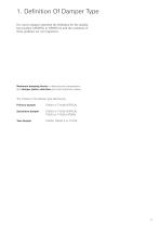
1. Definition Of Damper Type For correct damper operation the definition for the installation position LATERAL or VERTICAL and the variations of these positions are very important. Maximum damping forces in rebound and compression and damper piston velocities are most important values. The choises of the damper type defined are: Primary damper Secondary damper
Open the catalog to page 3
1.1 Technical Data Sheets Primary and secondary damper max. damping force, rebound [N] max. damping force, comp. [N] piston velocity [m/s] max. damping force, rebound [N] max. damping force, compr. [N] Secondary damper piston velocity [m/s] maximum static tensile load → without rebound stop [N] maximum angle to vertical → with mech. rebound stop [N] (eye mounting) → with mech. rebound stop [N] (stem mounting) diameter of dust shield D1 [mm] (damper with stroke < 400 mm) → standard design → screwed design diameter of outer tube D2 [mm] Non-symmetrical damping characteristics are also available....
Open the catalog to page 4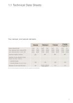
1.1 Technical Data Sheets Yaw damper and special dampers with continuous piston rod max. damping force, rebound [N] max. damping force, compr. [N] maximum angle to vertical see calc. of damper length (page 12) diameter of dust shield D1 [mm] (damper with stroke < 400 mm) → standard design → screwed design diameter of outer tube D2 [mm] Non-symmetrical damping characteristics are also available (except T60/42,5).
Open the catalog to page 5
2. Definition Of Damper Attachments Other important damper items are the attachments. The attachment TYPE affects directly the function (stiffness) and endurance life (bending moment) of the damper. Attachment parameters to be defined: ➔ Type of attachment for example: loop-loop stem-stem stem-loop loop-stem Attachment types loop-stem and stem-stem are only available for vertical dampers. Maximum conical, axial and radial deflection Attachment load Cradial and Caxial (mostly max. damping force) Definition of attachment design (see pages 8 - 11) 001 rubber bearing with trunnion rubber bearing/spheribloc...
Open the catalog to page 6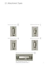
Attachment type: loop-loop Attachment type: stem-stem Attachment type: stem-loop Attachment type: loop-stem Attachment type for lateral and yaw dampers: loop-loop Mark “UNTEN/BOTTOM” must face towards ground in assembled condition
Open the catalog to page 7
Damper type Dimensions in [mm] Figures in bold are standard designs Max. angle movements are single loads (no overlay) Spring rates can vary depending on application Missing data available on request Deviations from standard mounts are available on request
Open the catalog to page 8
Damper type Dimensions in [mm] Max. angle movements are single loads (no overlay) Spring rates can vary depending on application Missing data available on request Deviations from standard mounts are available on request
Open the catalog to page 9
Damper type Dimensions in [mm] Figures in bold are standard designs Max. angle movements are single loads (no overlay) Spring rates can vary depending on application Missing data available on request Deviations from standard mounts are available on request
Open the catalog to page 10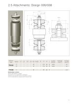
Damper type Dimensions in [mm] Missing data available on request Spring rates can vary depending on application Deviations from standard mounts are available on request Non-zinc plated parts are equipped with a protection cap
Open the catalog to page 11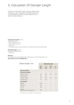
3. Calculation Of Damper Length In order to avoid metal to metal contact in rebound and compression, due to suspension and bogie tolerances, it is recommended to provide an extra stroke reserve of 10mm for both directions. Compressed Length (Lmin) = dead length (L-fix) + upper attachment (L1) + lower attachment (L2) + stroke (S) + mechanical rebound stop length (LA) optional (see technical data sheets). Extended length (Lmax) = compressed length (Lmin) + stroke (S) Attention: To calculate the compressed length of damper type with through piston rod the stroke has to be multiplied by 2. Dead length...
Open the catalog to page 12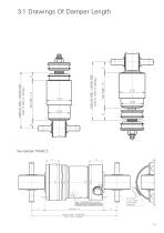
3.1 Drawings Of Damper Length Mark “UNTEN/BOTTOM” must face towards ground in assembled condition
Open the catalog to page 13
Paint ➔ Pre-treatment: zinc-phosphate Electrostatic painting with epoxy based 2K water based paint Coat thickness 30 - 50 µm Oven drying at ca. 110 °C Sand yellow Tarpaulin grey Platinum grey Brown beige Leaf green Iron grey Dusty grey Pure orange Olive green Basalt grey Agate grey Reseda green Slate grey Quartz grey Reed green Anthracite grey Yellow olive Black grey Grey brown Sapphire blue Squirrel grey Umbra grey Gentian blue Silver grey Concrete grey Graphite black Steele blue Signal grey Graphite grey Preferred colours in bold typefaces
Open the catalog to page 14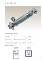
Identification (roll stamp on dirt shield) ZF Sachs railway dampers are generally provided with the following data: ZF Sachs part number - Type (PistOn/P. Rod dia. x stroke) - Damping resistances [N] at test velocities [m/s] Production date: week/year [e.g. 3505] Roll stamp plus adhesive label (standard design) Riveted plate (special design)
Open the catalog to page 15
ZF Sachs AG Railway Technology Bogestrasse 50 53783 Eitorf Germany Phone: +49 2243 12-383 Fax: +49 2243 12-280 [email protected] Driveline and Chassis Technology
Open the catalog to page 16
Questionnaire to be used in conjunction with GUIDELINES FOR DAMPER SELECTION AND CALCULATION ZF Sachs, Eitorf, Germany Dept.: DHR Phone: +49 2243 12-280 Fax: +49 2243 12-383 Address: Bogestrasse 50, 53783 Eitorf, Germany Company: Contact: Phone: Fax: End user/customer: Vehicle type: Bogie type: Damper type: primary/secondary/horizontal/vertical/yaw/ (Please underline applicable types Other, please state) Quantity of specified damper per bogie/vehicle: Total production volume: Service conditions: Minimum life: Static rebound load: Service temperatures: Extreme temperatures: Definition Damper position...
Open the catalog to page 17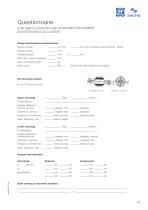
ft^d SACHS to be used in conjunction with GUIDELINES FOR DAMPER Design detail/physical characteristics Damper length: _ mm min. _ mm max. (includes reserve □ Yes □ No) Max. diam. space envelope: _ mm Paint colour: _ RAL (Default RAL 9005 black if not stated) p degree, conical a degree, torsiona Upper mounting Angular deflection (normal service) Static deflection rate kN/mm radial Lower mounting Angular deflection (normal service): Static deflection rate: kN/mm radial Damper characteristics Test stroke: Rebound Compression State drawing or document numbers:
Open the catalog to page 18All ZF Friedrichshafen AG catalogs and technical brochures
 ZF Duoplan 2K
40 Pages
 Innovations of Great Value.
9 Pages
 ZF-Single-disc
20 Pages
 ZF-Servoplan PG
16 Pages
 ZF-Tiratron
28 Pages
 ZF Swing Gearboxes
16 Pages
 ZF Drive Gearboxes
24 Pages
 Moving the big things
13 Pages
 ZF Eco liFE Rail
2 Pages
 ZF IS EFFICIENCY
23 Pages
 ZF MIXES the world
4 Pages
 Suspension Springs for PC
886 Pages
 TraXon at a Glance
2 Pages
 Experiencing Dynamics - reliably
15 Pages
 CV Chassis Modules
8 Pages
 Swing gearboxes GFB
16 Pages
 Gearboxes for winches GPT-W
5 Pages
 GEARBOXES FOR WINCHES
16 Pages
 Drive gearboxes GPT/GFA
24 Pages
 ZF. Network of Competence
8 Pages
 DMU Driveline System
2 Pages
 Bow Thruster
4 Pages
 Windenergy Image
4 Pages
 T-7000 tractor transaxle
2 Pages


- Planetary gearbox
- Coaxial gearhead
- Precision gearhead
- Compact gearhead
- Gear train gear reducer
- Multi-stage gearhead
- Helical gear gearhead
- Dual-stage gearbox
- High-performance gearhead
- High-precision gearhead
- High-torque gearhead
- High-efficiency gearhead
- Electric motor gearhead
- Maintenance-free gear reducer
- Servo motor gearhead
- Machine tool gear reducer
- Clutch and brake
- Friction clutch and brake
- Cutting machine gear reducer
- Manual gear reducer