- Catalogs
- Zander GmbH & Co. KG, Hermann
- Safety Relay SRLC
Safety Relay SRLC
1 /4Pages

Safety Relay SRLC
1 /4Pages
Catalog excerpts
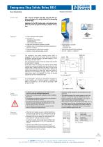
Emergency Stop Safety Relay SRLC User Information Correct Use English translation SRLC is low-cost emergency stop safety relay with which machines and systems can be safely switched off by disconnecting the power supply. Applications for the SRLC include single or dual-channel emergency stop circuits and guard monitoring on machines and systems. • 2 safe, redundant relay outputs (not for plug-in terminals) - Emergency stop buttons - Safety switches - Non-contact safety switches Single and dual-channel operation possible Feedback loop for monitoring downstream contactors or expansion modules Cyclical monitoring of the output contacts Indication of the switching state via LED The emergency stop safety switching device SRLC is designed for safe isolation of safety circuits according to EN 60204-1 and can be used up to safety category 3, PL d according to EN ISO 13849-1. The internal logical system closes the safety contacts when the start button is pressed. If the safety switch is opened, the positively driven safety contacts are opened and safely switch the machine off. It is ensured that a single fault does not lead to a loss of the safety function and that every internal fault is detected by cyclical self-monitoring no later than when the system is switched off and switched on again. Only a fault in the safety switch itself is not detected. This must be checked regularly as part of a maintenance plan. • 2 start behaviors possible: - Manual start - Automatic start • Short circuit and earth fault monitoring • Up to PL d, SILCL 2, category 3 Fig. 1 Block diagram SRLC As per EN 60204-1, the device is intended for installation in control cabinets with a minimum degree of protection of IP54. It is mounted on a 35 mm DIN rail according to DIN EN 60715 TH35. Safety Precautions • Installation and commissioning of the device must be • • • Electrical Connection performed only by authorized personnel. Observe the country-specific regulations when installing the device. The electrical connection of the device is only allowed to be made with the device isolated. The wiring of the device must comply with the instructions in this user information, otherwise there is a risk that the safety function will be lost. It is not allowed to open the device, tamper with the device or bypass the safety devices. • When the 24 V version is used, a control transformer according to EN 61558-2-6 or a power supply unit with electrical isolation from the mains must be connected. External fusing of the contacts (4 A slow-blow or 6 A quick-action or 10 A gG) must be provided. A maximum length of the control lines of 1000 meters with a line cross section of 0.75 mm2 must not be exceeded. The line cross section must not exceed 2.5 mm2. If the device does not function after commissioning, it must be returned to the manufacturer unopened. Opening the device will void the warranty. • All relevant safety regulations and standards are to be observed. • The overall concept of the control system in which the device is incorporated must be validated by the user. • Failure to observe the safety regulations can result in death, serious injury and serious damage. • Note down the version of the product (see label “Ver: x”) and check it prior to every commissioning of a new device. If the version has changed, the overall concept of the control system in which the device is incorporated must be validated again by the user. Power supply Power supply DC 24 V control voltage Control line Safety contact 1 Safety contact 2 H. ZANDER GmbH & Co. KG • Am Gut Wolf 15 • 52070 Aachen • Germany Tel +49 (0)241 9105010 • Fax +49 (0)241 91050138 • [email protected] • www.zander-aachen.de
Open the catalog to page 1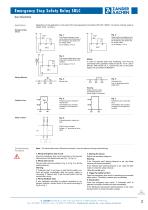
Emergency Stop Safety Relay SRLC User Information Applications Depending on the application or the result of the risk assessment according to EN ISO 13849-1, the device must be wired as shown in Fig. 1 to Fig. 8. Emergency Stop Circuit Two-channel emergency stop circuit without fault monitoring of the emergency stop button and the supply cables. (up to category 3, PL d) Single-channel emergency stop circuit without fault monitoring of the emergency stop button and the supply cables. (up to category 1, PL c) Fig. 3: Two-channel sliding guard monitoring with positively driven limit switches. (up...
Open the catalog to page 2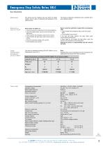
Emergency Stop Safety Relay SRLC User Information Maintenance The device must be checked once per month for proper function and for signs of tampering and bypassing of the safety function. The device is otherwise maintenance free, provided that it was installed properly. What to Do in Case of a Fault? Device does not switch on: • Check the wiring by comparing it to the wiring diagrams. • Check the safety switch used for correct function and adjustment. • Check whether the emergency stop circuit is closed. • Check whether the start button (with manual start) is closed. • Check the operating voltage...
Open the catalog to page 3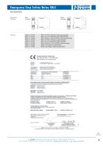
Emergency Stop Safety Relay SRLC User Information Order no. 472160 SRLC, AC 230 V (50-60 Hz), fixed screw terminals Order no. 472161 SRLC, AC 115 V (50-60 Hz), fixed screw terminals Order no. 472162 SRLC, AC/DC 24 V (AC: 50-60 Hz), fixed screw terminals Order no. 473160 SRLC, AC 230 V (50-60 Hz), plug-in terminals_ Order no. 473161 SRLC, AC 115 V (50-60 Hz), plug-in terminals_ Order no. 473162 SRLC, AC/DC 24 V (AC: 50-60 Hz), plug-in terminals Order no. 472592 EKLS4, set of plug-in screw terminals_ Order no. 472593 EKLZ4, set of plug-in tensile spring terminals Am Gut Wolf 15 - 52070 Aachen •...
Open the catalog to page 4All Zander GmbH & Co. KG, Hermann catalogs and technical brochures
 Safety time control device
8 Pages
 Safety Relay MINOS SD1E
16 Pages
 Safe Coupling Relay MINOS SD1K
14 Pages
 Zander Aachen - Automation
55 Pages
 ZX20T HIGH SPEED CONTROLLER
8 Pages
 ZCode-MZ
2 Pages
 TALOS TB-l 1403
8 Pages
 MINOS Product line
22 Pages
 Safety & Automation
12 Pages
 Product Catalogue
59 Pages
 Microswitch KL
3 Pages
 Multifunction Timer DMC
2 Pages


- Angular encoder
- Digital I/O
- Single-pole switch
- IO module
- Digital IO module
- Technology switch
- Absolute rotary encoder
- Multipole switch
- Solid-shaft rotary encoder
- Programmable logic controller
- Fieldbus I/O module
- Electromechanical switch
- Serial I/O
- Time relay
- Rotary electric switch
- IP67 switch
- Serial I/O module
- Metal switch