- Catalogs
- Zander GmbH & Co. KG, Hermann
- Safety Relay MINOS SD1E
Safety Relay MINOS SD1E
1 /16Pages

Safety Relay MINOS SD1E
1 /16Pages
Catalog excerpts

MINOS SD1E Product Information Safety Relay MINOS SD1E
Open the catalog to page 1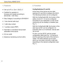
Safety Relay MINOS SD1E 1. Features Use up to PL e, Cat. 4, SILCL 3 At the back of the device are two slideswitches (S1 and S2) to configure the SD1E. The following functions can be configured: furnaces and vessels according to EN 50156-1 / EN 746-2 Stop Category 0 according to EN 60204-1 1 two-channel safe input 1 safe relay contact 1 auxiliary output (PNP) Automatic or monitored manual start selectable at the device 6.8 mm width Extensive monitoring via front LED‘s With the Config-Switch S1, the function of the safety circuit at I1 / I2 can be configured. According to your application...
Open the catalog to page 2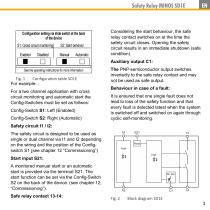
Safety Relay MINOS SD1E Considering the start behaviour, the safe relay contact switches on at the time the safety circuit closes. Opening the safety circuit results in an immediate shutdown (safe condition). Auxiliary output C1: Fig. 1 Configura on table SD1E For example: For a two channel application with cross circuit monitoring and automatic start the Config-Switches must be set as follwos: Config-Switch S1: Left (Enabled) Config-Switch S2: Right (Automatic) The PNP-semiconductor output switches invertedly to the safe relay contact and may not be used as safe output. Behaviour in case of a...
Open the catalog to page 3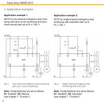
Safety Relay MINOS SD1E 3. Application examples Application example 1: SD1E for two-channel emergency stop monitoring with short circuit monitoring and monitored manual start up to PL e / SIL 3. SD1E for single-channel emergency stop monitoring with automatic start up to PL c / SIL 1. Two-channel emergency-stop monitoring with cross circuit monitoring Note: Config-Switches are set as follows: S1: Enabled / S2: Manual (see chapter 7. “Function”) 4 Single-channel emergency stop monitoring with auto-start Note: Config-Switches are set as follows: S1: Disabled / S2: Automatic (see chapter 7. “Functio...
Open the catalog to page 4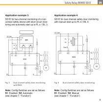
Safety Relay MINOS SD1E SD1E for two-channel monitoring of a noncontact safety device with short circuit monitoring and automatic start up to PL e / SIL 3. SD1E for dual channel safety door monitoring with manual start up to PL e / SIL 3. Dual channel safety door monitoring with BWS Note: Config-Switches are set as follows: S1: Enabled / S2: Automatic (see chapter 7. “Function”) Dual channel safety door monitoring Note: Config-Switches are set as follows: S1: Enabled / S2: Manual (see chapter 7. “Function
Open the catalog to page 5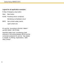
Safety Relay MINOS SD1E Legend for all application examples: E-Stop: Emergency stop button Start: Start button KA/KB: Positively driven contactors; Monitoring via feedback circuit BWS: Non-contact safety switch, Light curtains etc. PL and SIL: According to EN ISO 13849-1 and IEC 62061 / IEC 61508. Specified safety level, considering a fault exclusion in the wiring between SD1E and the connected contactors KA and KB. See details in chapter 15 "Wiring / Applications - Safe relay contact”
Open the catalog to page 6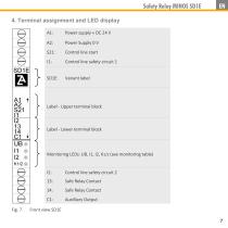
Safety Relay MINOS SD1E 4. Terminal assignment and LED display A1: Control line start Control line safety circuit 1 Variant label Label - Upper terminal block Label - Lower terminal block Monitoring LEDs: UB, I1, I2, K1/2 (see monitoring table) Control line safety circuit 2 Safe Relay Contact Safe Relay Contact Auxilliary Output
Open the catalog to page 7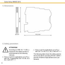
Safety Relay MINOS SD1E 5. Dimensions 6. Safety parameters ATTENTION! According to CNB / M / 11.050, a request for the safety function is recommended at the following intervals: Once a month for applications up to PL e with Cat. 3 respectively Cat. 4 or SIL CL3, SIL 3 with HFT = 1 8 Once a year for applications up to PL d with Cat. 3 or SIL CL 2, SIL 2 with HFT = 1 The following table shows the safety parameters for the SD1E according EN ISO 13849-1 and IEC 61508 for High-Demand and LowDemand
Open the catalog to page 8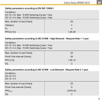
Safety Relay MINOS SD1E Safety parameters according to EN ISO 13849-1 Conditions: AC-15: 5 A; Max. 10.000 Switching-Cycles / Year DC-13: 4 A; Max. 15.000 Switching-Cycles / Year Max. duration of use [Years] Safety parameters according to IEC 61508 - High-Demand - Request Rate < 1 year Conditions: AC-15: 5 A; Max. 10.000 Switching-Cycles / Year DC-13: 4 A; Max. 15.000 Switching-Cycles / Year Max. duration of use [Years] Proof-Test-Intervall [Years] PFH [1/h] SIL Safety parameters according to IEC 61508 - Low-Demand - Request Rate ≥ 1 year Conditions: AC-15: 5 A DC-13: 4 A Max. duration of use...
Open the catalog to page 9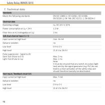
Safety Relay MINOS SD1E 7. Technical data Standards Meets the following standards Electrical data Opera ng voltage Safe dual-channel input I1 / I2 Input current at high level High level Pulse suppression - Signal to 0V Dark-Test (Pulse to 0 V) Light-Test (Pulse to UB) Max. 5 ms Max. 1 ms Note: It must be ensured that any switch-on pulses (light test) sent by the signal generator (e.g. PLC) do not lead to a short ac va on of the safety relay and should therefore basically be deac vated. Start input / feedback circuit S21 Input current at high level High level
Open the catalog to page 10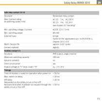
Safety Relay MINOS SD1E Safe relay contact 13-14 Structure Redundant relay contact Max. Contact ra ng (6 switching cycles/ min) Min. switching voltage / current Min. switching power External fuses Mech. Service life Contact material 6 A gG Factor 0.6 for applica ons acc. to EN 50156-1, chapter 10.5.5.3.4 approx. 1x10⁷ cycles AgSnO2 Auxiliary output C1 Structure Maximum switching capacity Galvanic isola on PNP output, single channel 100 mA no Short-circuit-proof Output voltage at "1" (max. load) / "0" Timings Time ll module is ready for opera on aIer power-on < 50 ms Max. switch-on delay < 20...
Open the catalog to page 11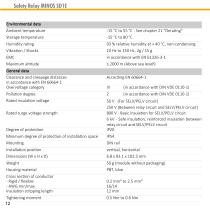
Safety Relay MINOS SD1E Environmental data Ambient temperature Storage temperature Humidity ra ng Vibra on / Shocks 93 % rela ve humidity at + 40 °C, non-condensing 10 Hz to 150 Hz, 2g / 15 g in accordance with EN 61326-3-1 ≤ 2000 m (Above sea level9 General data Clearance and creepage distances in accordance with EN 60664-1 Overvoltage category Pollu on degree Rated insula on voltage (in accordance with DIN VDE 0110-1) (in accordance with DIN VDE 0110-1) Degree of protec on Minimum degree of protec on of installa on space 50 V (For SELV/PELV circuit) 250 V (Between relay circuit and SELV/PELV...
Open the catalog to page 12All Zander GmbH & Co. KG, Hermann catalogs and technical brochures
 Safety time control device
8 Pages
 Safe Coupling Relay MINOS SD1K
14 Pages
 Zander Aachen - Automation
55 Pages
 ZX20T HIGH SPEED CONTROLLER
8 Pages
 ZCode-MZ
2 Pages
 TALOS TB-l 1403
8 Pages
 MINOS Product line
22 Pages
 Safety & Automation
12 Pages
 Product Catalogue
59 Pages
 Microswitch KL
3 Pages
 Multifunction Timer DMC
2 Pages
 Safety Relay SRLC
4 Pages


