- Catalogs
- Zander GmbH & Co. KG, Hermann
- Safe Coupling Relay MINOS SD1K
Safe Coupling Relay MINOS SD1K
1 /14Pages

Safe Coupling Relay MINOS SD1K
1 /14Pages
Catalog excerpts

MINOS SD1K Product Information Safe Coupling Relay MINOS SD1K
Open the catalog to page 1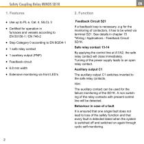
Safety Coupling Relay MINOS SD1K 1. Features If a feedback loop is necessary, e.g for the monitoring of contactors, it has to be wired via terminal S21. See details in chapter 15 "Wiring / Applications - Feedback Circuit SD1K. furnaces and vessels according to EN 50156-1 / EN 746-2 Stop Category 0 according to EN 60204-1 1 safe relay contact 1 auxiliary output (PNP) Feedback circuit 6.8 mm width Extensive monitoring via front LED‘s Safe relay contact 13-14 By applying the control line at A1/A2, the safe relay contact will close immediately. Turning of the power supply leads to an...
Open the catalog to page 2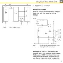
Safety Couple Relay MINOS SD1K 3. Application example Application example SD1K as contact reinforcement and test pulse filtering for safe PLC output up to PL e/ SILCL 3 Contact reinforcement and test pulse filtering for safe PLC outputs Prerequisite: Safe PLC output meets the required safety level and short circuit between PLC output and SD1K can be excluded (e.g. wiring inside an electrical installation space see EN ISO 13849-2:2013:02, Tab D4 / D5). 3
Open the catalog to page 3
Safety Coupling Relay MINOS SD1K Legend KA/KB: Positively driven contactors; Monitoring via feedback circuit PL and SILCL: According to EN ISO 13849-1 and IEC 62061. Specified safety level, considering a fault exclusion in the wiring between SD1K and the connected contactors KA and KB. See details in chapter 15 "Wiring / Applications - Safe relay contact”:
Open the catalog to page 4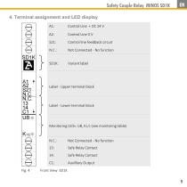
Safety Couple Relay MINOS SD1K 4. Terminal assignment and LED display A1: Control line feedback circuit Variant label Label - Upper terminal block Label - Lower terminal block Monitoring LEDs: UB, K1/2 (see monitoring table) Safe Relay Contact Safe Relay Contact Auxilliary Output
Open the catalog to page 5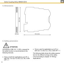
Safety Coupling Relay MINOS SD1K 5. Dimensions ATTENTION: According to CNB / M / 11.050, a request for the safety function is recommended at the following intervals: Once a month for applications up to PL e with Cat. 3 or Cat. 4 or SIL CL3, SIL 3 with HFT = 1 6 Once a year for applications up to PL d with Cat. 3 or SIL CL 2, SIL 2 with HFT = 1 The following table shows the safety parameters for the different wirings of the safety circuit according to chapter 15 "Wiring / Applications"
Open the catalog to page 6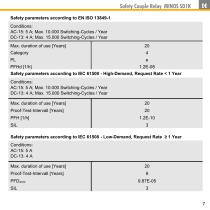
Safety Couple Relay MINOS SD1K Safety parameters according to EN ISO 13849-1 Conditions: AC-15: 5 A; Max. 10.000 Switching-Cycles / Year DC-13: 4 A; Max. 15.000 Switching-Cycles / Year Max. duration of use [Years] PFHd [1/h] 1.2E-08 Safety parameters according to IEC 61508 - High-Demand, Request Rate < 1 Year Conditions: AC-15: 5 A; Max. 10.000 Switching-Cycles / Year DC-13: 4 A; Max. 15.000 Switching-Cycles / Year Max. duration of use [Years] Proof-Test-Intervall [Years] PFH [1/h] SIL Safety parameters according to IEC 61508 - Low-Demand, Request Rate ≥ 1 Year Conditions: AC-15: 5 A DC-13: 4...
Open the catalog to page 7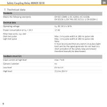
Safety Coupling Relay MINOS SD1K 7. Technical data Standards Meets the following standards Electrical data Operating voltage Filter time at A1, UB= 2kV Dark test pulse Light test pulse Max. 2 ms pulse width at 200 ms pulse rate Max. 1 ms pulse width at 200 ms pulse rate Note: It must be ensured that any switch-on pulses (light test) sent by the signal generator do not lead to a short activation of the safety relay and should therefore basically be deactivated. Feedback circuit S21 Input current at high level Galvanic isolation High level
Open the catalog to page 8
Safety Couple Relay MINOS SD1K Safe relay contact 13-14 Structure Max. Contact rating (6 switching cycles/ min) Redundant relay contact Min. switching voltage / current Min. switching power External fuses AC/DC 12 V / 3 mA 60 mW 6 A gG Factor 0.6 for applications acc. to EN 50156-1, chapter 10.5.5.3.4 approx. 1x10⁷ cycles Mech. Service life AC-15: 5 A, AC 230 V DC-13: 4 A, DC 24 V See derating characteristics in chapter 21. Contact material Auxiliary output C1 Structure Maximum switching capacity Galvanic isolation Short-circuit-proof Output voltage at "1" (max. load) / "0" Timings Time till...
Open the catalog to page 9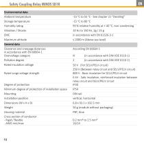
Safety Coupling Relay MINOS SD1K Environmental data Ambient temperature Storage temperature Humidity rating Vibration / Shocks EMC Maximum altitude General data Clearance and creepage distances in accordance with EN 60664-1 Overvoltage category Pollution degree -15 °C to 80 °C 93 % relative humidity at + 40 °C, non-condensing 10 Hz to 150 Hz, 2g / 15 g in accordance with EN 61326-3-1 ≤ 2000 m (Above sea level) Rated insulation voltage 50 V (For SELV/PELV circuit) 250 V (Between relay circuit and SELV/PELV circuit) 800 V - Basic insulation for SELV/PELV circuit 6 kV - Safe insulation, reinforced...
Open the catalog to page 10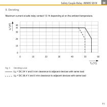
Safety Couple Relay MINOS SD1K 8. Derating Maximum current at safe relay contact 13-14 depending at on the ambient temperature. Derating curve UB = DC 24 V and 0 mm clearance to adjacent devices with same load UB = DC 26,4 V and 0 mm clearance to adjacent devices with same load
Open the catalog to page 11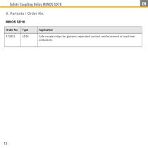
Safety Coupling Relay MINOS SD1K 9. Variants / Order No. MINOS SD1K Order No. Safe couple relays for galvanic separated contact reinforcement at machines and plants.
Open the catalog to page 12
Safety Couple Relay MINOS SD1K 10. Contact / Service For service requirements, contact H. Zander GmbH & Co. KG Am Gut Wolf 15 52070 Aachen Germany Service line +49 241 910 501-0 E-mail [email protected] Internet www.zander-aachen.de
Open the catalog to page 13
Safety Coupling Relay MINOS SD1K
Open the catalog to page 14All Zander GmbH & Co. KG, Hermann catalogs and technical brochures
 Safety time control device
8 Pages
 Safety Relay MINOS SD1E
16 Pages
 Zander Aachen - Automation
55 Pages
 ZX20T HIGH SPEED CONTROLLER
8 Pages
 ZCode-MZ
2 Pages
 TALOS TB-l 1403
8 Pages
 MINOS Product line
22 Pages
 Safety & Automation
12 Pages
 Product Catalogue
59 Pages
 Microswitch KL
3 Pages
 Multifunction Timer DMC
2 Pages
 Safety Relay SRLC
4 Pages


- Angular encoder
- Digital I/O
- Single-pole switch
- IO module
- Digital IO module
- Technology switch
- Absolute rotary encoder
- Multipole switch
- Solid-shaft rotary encoder
- Fieldbus I/O module
- Electromechanical switch
- Safety electric switch
- Serial I/O
- Time relay
- Limit switch
- Rotary electric switch
- IP67 switch
- Serial I/O module
- Metal switch