- Catalogs
- YZ Systems
- NJEX 7300G
NJEX 7300G
1 /129Pages

NJEX 7300G
1 /129Pages
Catalog excerpts

The NJEX 7300G Instruction & Operating Manual Version: 06-2022
Open the catalog to page 3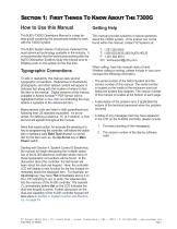
Section 1: First Things To Know About The 7300G How to Use this Manual Getting Help The NJEX-7300G Operations Manual is a step-bystep guide containing the procedures needed to work with the 7300G System. This manual provides solutions to typical questions about the 7300G system. If the answer can not be found within this manual, contact YZ Systems at: The NJEX System Series of odorizers implement the T: 1.281.362.6500 most advanced technology available in the industry. It T: 1.800.653.9435 (800.NJEX.HELP) is recommended that the technicians working with the F: 1.281.362.6513 NJEX Odorization...
Open the catalog to page 11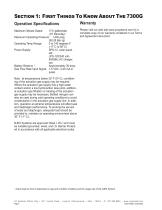
Section 1: First Things To Know About The 7300G Operation Specifications Please visit our web site www.yzsystems.com for a Maximum Odorant Output: 17.6 gallons/day complete copy of our warranty contained in our Terms (67 liters/day) and Agreement document. Maximum Operating Pressure: 1,440 psig (99.28 Bar (g) Operating Temp Range: 0 to 140 degrees F. (-17°C to 60°C) Power Supply: SPS-12 solar panel , std. LPS-120/240 volt- 50/60Hz AC charger, opt. Battery Reserve 1: Approximately 30 days Gas Flow Rate Input Signal: 1-5 VDC, 4-20 mA or pulse Note: at temperatures below 32º F (0º C), conditioning...
Open the catalog to page 12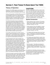
Section 1: First Things To Know About The 7300G Theory of Operation Excessive tubing lengths should be avoided. Installation of the NJEX Odorization system should be as close to the point of injection and Odorant Storage Tank as possible. Maximum tubing length should not During normal operation, the Model 7000 pump injects exceed 15’ (4.5 meters) with the tubing size mainan exact quantity of odorant at a rate determined tained as indicated in this manual. If longer tubing by the N-300G controller. The quantity of odorant lengths are required consult YZ Systems Technical injected per stroke is...
Open the catalog to page 13
Section 1: First Things To Know About The 7300G Notes
Open the catalog to page 14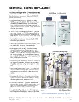
Section 2: System Installation Standard System Components • SPS12 Solar Panel Assembly Standard primary components of the NJEX-7300G include the following: • System Enclosure, figure 1. Houses the Model 7000F pump, the Model VM-1100 Verometer, the odorant fill valve, the solenoid valve/pneumatic relay manifold, the odorant discharge manifold, the system control enclosure, *power supply enclosure, and bulk odorant filter. Expansion Tank System Enclosure • *SPS12 Solar Panel Assembly, figure 1. The standard solar panel for the 7300G is equipped with a mounting bracket and a connection cable.Optional...
Open the catalog to page 15
Section 2: System Installation System Flow Schematic Figure 4
Open the catalog to page 16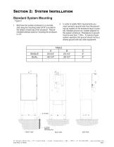
Section 2: System Installation Standard System Mounting Figure 5 2. In order to satisfy NEC requirements you must connect a ground wire from the grounding lug located on the enclosure leg to a properly installed ground rod, located adjacent to the system enclosure. *Resistance to ground must be less than 1 Ohm. To assure proper system operation this ground should not be a shared ground with any other equipment. 1. Bolt down the system enclosure to a concrete slab using the mounting holes (9/16”) provided in the bottom of each leg of the enclosure. Recommended bolt/stud sizes for mounting the...
Open the catalog to page 17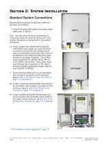
Section 2: System Installation Standard System Connections Required field connections to place the 7300G into operation are as follows: 1. Connect the solar panel cable to the system power supply, sps-12, figure 6. Note: the solar panel should be mounted free of obstructing shade and should be facing south in the northern hemisphere or facing North in the southern hemisphere. 1a. *If your system was ordered with the optional LPS120/240 power supply, AC power should be connected in accordance with explosion-proof code via a termination junction box (not shown) to be attached to the conduit provided...
Open the catalog to page 18
Section 2: System Installation CAUTION: 6. Excessive tubing lengths should be avoided. Installation of the NJEX Odorization system should be as close to the point of injection and Odorant Storage Tank as possible. Maximum tubing length should not exceed 15’ (4.5 meters) with the tubing size maintained as indicated in this manual. If longer tubing lengths are required consult YZ Systems Technical Service Department at; 800.653.9435 or 281.362.6500. 3. Connect the odorant supply source to the odorant inlet mainfold with the recommended 1/4” stainless If a heater option was specified with this odorizer,...
Open the catalog to page 19
Section 2: System Installation The NJEX SkidMount Series of odorization systems is a total system approach to odorization. These systems are completely factory assembled, tested, and delivered requiring only three field connections to be fully operational. The NJEX SkidMount Systems offer all the advantages of our standard 7300G Systems plus the added benefit of an onboard odorant storage tank. The configuration allows for a total systems approach to odorization. The SkidMount Systems come standard with an electronic level indicator factory connected to the N-300G controller. The controller has...
Open the catalog to page 20
Section 2: System Installation • Bulk Odorant Filter, figure 12, provides primary odorant filtration between the storage tank and the NJEX-7300G. The bulk odorant filter is preinstalled inside the system enclosure attachment to the odorant source is via a bulk filter manifold equipped with 1/4” FNPT connection located on the back of the system enclosure. • Mechanical Interconnect Cable, figure 12, provides the connection between the system control enclosure and the electrical components located in the mechanical section. • Expansion Tank, figure 13, provides a closed loop system for pressure...
Open the catalog to page 21
Section 2: System Installation System Flow Schematic
Open the catalog to page 22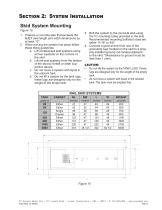
Section 2: System Installation Skid System Mounting Figure 15 1. Prepare a concrete slab that exceeds the NJEX skid length and width dimensions by at least 12”. 2. When moving the system into place follow these lifting guidelines: a. Lift containment skid systems using all four eyebolts on the corners of the skid. b. Lift rail skid systems from the bottom of the skid by forklift or other supportive device. c. Do not move a system with liquid in the odorant tank. d. Do not lift a system by the tank lugs, these lugs are designed only for the weight of the empty tank. CABINET Either Either Single...
Open the catalog to page 23All YZ Systems catalogs and technical brochures
 Cyclone 4400
36 Pages
 njex-6300-datasheet
129 Pages
 YZ Connect
1 Page
 Crude Oil Sampling Systems
2 Pages
 Odorization Systems
8 Pages


- Windows software
- Real-time software
- Gas detector
- Monitoring software solution
- Communication gateway
- Ethernet gateway
- Fieldbus gateway
- Wireless gateway
- Portable detector
- IoT gateway
- Greasing system
- Oil greasing system
- Modbus gateway
- Modbus RTU gateway
- Liquid sampler
- Cellular gateway
- Modbus TCP gateway
- Android software
- Gas sampler
- IOS software