- Catalogs
- YUKEN Europe Ltd.
- Throttle (& Check) Modules
Throttle (& Check) Modules
1 /7Pages

Throttle (& Check) Modules
1 /7Pages
Catalog excerpts
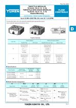
FLOW CONTROLS Specifications / Model Number Designation Up to 25 MPa (3630 PSI), 80 L/min (21.1 U.S.GPM) Used as pilot choke valves for solenoid controlled pilot operated directional valves and pilot operated directional valves. D Graphic Symbols Throttle Modules Throttle and Check Modules Valve Size Standard Type With Check Solenoid Operated Directional Valve Standard (Metre-out) Type Metre-in Type Solenoid Operated Directional Valve Solenoid Operated Directional Valve Solenoid Operated Directional Valve Solenoid Operated Directional Valve Solenoid Operated Directional Valve Specifications Model Numbers TC1G-01-40/4090 TC2G-01-40/4090 TC1G-03-∗-40/4090 Nominal Flow L /min (U.S.GPM) Model Number Designation FTC1 Special Seals Series Number Valve Size F-: Special Seals for Phosphate Ester Type Fluids (Omit if not required) TC2: Throttle and Check Module Valve Type Design Number Design Standards None: Std. Type G: Gasket Mounting None: Std. (Metre-Out) Type 40 None: Japanese Std. "JIS" and European Design Std. None: Std. Type C: With Check Valve TC2: Throttle and Check Module None: Std. (Metre-Out) Type A: Metre-in Type
Open the catalog to page 1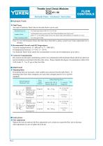
Throttle (and Check) Modules TC1G -01 / 03 TC2G FLOW CONTROLS Hydraulic Fluids / Attachment / Instructions Hydraulic Fluids Fluid Types Any type of hydraulic fluids listed in the table below can be used. Petroleum base oils Synthetic fluids Use phosphate ester or polyol ester fluid. When phosphate ester fluid is used, prefix "F-" to the model number because the special seals (fluororubber) are required to be used. Water containing fluids Note: For use with hydraulic fluids other than those listed above, please consult your Yuken representatives in advance. Recommended Viscosity and Oil Temperatures...
Open the catalog to page 2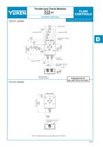
Throttle (and Check) Modules TC1G -01 TC2G FLOW CONTROLS Installation Drawings Mounting surface: ISO 4401-AB-03-4-A Lock Nut 12(.47) Hex. Pressure Port "P" Flow Adjustment Screw 6(.24) Hex. INC. 15 (.59) 25 (.98) Mounting Surface (O-Rings Furnished) DIMENSIONS IN MILLIMETRES (INCHES) 21.5 (.85) Flow Adjustment Screw 6(.24) Hex. INC. Note: For other dimensions, see the figures shown TC2G-01.
Open the catalog to page 3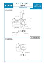
Throttle (and Check) Modules TC1G -03 TC2G FLOW CONTROLS Installation Drawings Mounting surface: ISO 4401-AC-05-4-A Pressure Port "P" Cylinder Port "B" Flow Adjustment Screw 7(.28) Hex. INC. Mounting Surface (O-Rings Furnished) With standard sub-plates, the left one of the two tank ports "T" is used but either one may be used. DIMENSIONS IN MILLIMETRES (INCHES) Flow Adjustment Screw 7(.28) Hex. INC. Note: For other dimensions, see the figures shown TC2G-03.
Open the catalog to page 4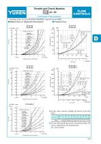
Throttle (and Check) Modules TC1G -01 / 03 TC2G FLOW CONTROLS Hydraulic Fluid: Viscosity 35 mm /s (164 SSU) , Specific Gravity 0.850 Metred Flow vs. Adjustment Revolutions TC1G-01 TC2G-01 Flow Rate Differential Pressure Pressure Drop Pressure Drop Adjustment Screw Revolutions Flow Rate Flow Rate Pressure Drop Differential Pressure Adjustment Screw Revolutions 0 Flow Rate U.S.GPM L/min 22.5 80 20 70 Flow Rate For any other viscosity, multiply the factors in the table below. For any other specific gravity (G'), the pressure drop ( P') may be obtained from the formula below. P'= P (G'/0.850) Adjustment...
Open the catalog to page 5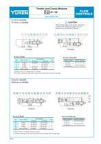
Throttle (and Check) Modules TC1G -01 / 03 TC2G FLOW CONTROLS Spare Parts List TC1G-01-40/4090 TC1G-03-∗-40/4090 CAUTION When making replacement of seals, please do it carefully after reading through the relevant instructions in the Operator's Manual. List of Seal Kits Name of Parts O-Ring O-Ring O-Ring Back Up Ring With TC1G-01, 4 O-Rings, Item 7 , are used. Note: When ordering the seals, please specify the seal kit number from the table right List of Seals Item O-Ring O-Ring O-Ring Back Up Ring With TC2G-01, 4 O-Rings, Item 22 , are used. Note: When ordering the seals, please specify the seal...
Open the catalog to page 6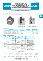
FLOW CONTROLS Threaded Connections / Sub-plate Mounting Specifications / Model Number Designation Up to 21 MPa (3050 PSI), 200 L/min (52.8 U.S.GPM) These valves are available either with or without an integral check valve which allows free reverse flow. Flow rate through the valve is regulated by the movement of the spool, which is operated by a cam. When the spool is depressed, the flow is decreased in Normally Open type valves and increased in Normally Closed type valves. Their principal use is to control the speed of actuators in machine tools and similar applications. Normally Open Type Normally...
Open the catalog to page 7All YUKEN Europe Ltd. catalogs and technical brochures
 DP SJT
1 Page
 BUCG
BUCG6 Pages
 BG BT
BG BT7 Pages
 DT-02, DG-02 series
3 Pages
 ASE series
4 Pages
 Flow Control Valve
1 Page
 A3HG Piston Pump
2 Pages
 "A" Series Piston Pumps
20 Pages
 SERVO VALVES
3 Pages
 Unloading Relief Valve
7 Pages
 04 Modular
8 Pages
 A7H Pump
8 Pages
 RELIEF VALVES
37 Pages
 VANE PUMPS
4 Pages
 PVR series
1 Page
 Linear Servo Valve
15 Pages
 Modular Valves
1 Page
 Pressure Control Valves
1 Page
 Linear Servo Valve
15 Pages
 "PV2R" SERIES
32 Pages
 "A" SERIES PISTON PUMPS
92 Pages


Archived catalogs
 Yuken General Catalogue
1765 Pages
- Lumibird pump
- Lumibird industrial pump
- Lumibird stationary pump
- Lumibird water pump
- Lumibird control valve
- Lumibird lubricant pump
- Lumibird oil pump
- Lumibird suction pump
- Lumibird regulating valve
- Lumibird flap valve
- Lumibird electric valve
- Lumibird piston pump
- Directional control valve
- Lumibird food product pump
- Lumibird discharge pump
- Lumibird standard pump
- Standard valve
- Lumibird hydraulic valve