- Catalogs
- YUKEN Europe Ltd.
- RELIEF VALVES
RELIEF VALVES
1 /37Pages

RELIEF VALVES
1 /37Pages
Catalog excerpts

RELIEF VALVES Remote Control / Direct Type Pilot Operated / Solenoid Controlled PRESSURE CONTROLS This valve is used as a remote control valve for pilot operated type pressure control valves.
Open the catalog to page 1
RELIEF VALVES Remote Control / Direct Type Pilot Operated / Solenoid Controlled Instructions / Hydraulic Fluids PRESSURE CONTROLS CAUTION When making replacement of seals or solenoid assemblies, please do it carefully after reading through the relevant instructions in the Operator's Manual. Instructions To adjust the pressure, loosen the lock nut and turn the handle slowly clockwise for higher pressures or anti-clockwise for lower pressures. After adjustments, do not forget to tighten the lock nut. Piping of the tank line should not be connected to any tank line of the other valves, but connected...
Open the catalog to page 2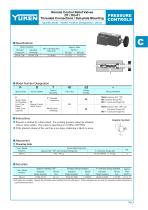
Remote Control Relief Valves DT / DG-01 Threaded Connections / Sub-plate Mounting Specifications / Model Number Designation / others PRESSURE CONTROLS Specifications Model Numbers Threaded Sub-plate Connection Mounting DG-01-22∗ DT-01-22∗ Model Number Designation FD Special Seals F: Special Seals for Phosphate Ester Type Fluids (Omit if not required) Series Number D: Remote Control Relief Valves Approx. Mass kg (lbs.) DT type DG type 1.6 (3.5) 1.4 (3.1) Valve Size Design Number Design Standards None: Japanese Std. "JIS" 80: European Design Std. 90: N. American Design Std. None: Japanese Std....
Open the catalog to page 3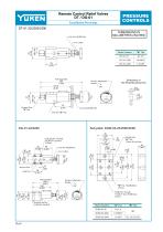
Remote Control Relief Valves DT / DG-01 PRESSURE CONTROLS DIMENSIONS IN MILLIMETRES (INCHES) Dimensions of The Panel Mounting Hole Pressure Adjustment Handle INC. 7(.28) Dia. Through 11(.43) C' bore 7(.28) Deep 2 Places Pressure Adjustment Handle 6.2(.24) Dia. "A" Thd. 2 Places (From Rear) Pressure Port Tank Port 5.5(.22) Dia. Through 9(.35) Dia. Spotface 4 Places
Open the catalog to page 4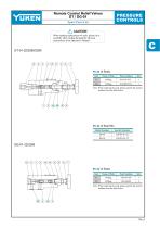
Remote Control Relief Valves DT / DG-01 PRESSURE CONTROLS Spare Parts List CAUTION When making replacement of seals, please do it carefully after reading through the relevant instructions in the Operator's Manual. List of Seals Item Parts Numbers Note: When ordering the seals, please specify the seal kit number from the table below. List of Seal Kits Model Numbers List of Seals Item Parts Numbers Note: When ordering the seals, please specify the seal kit number from the table below.
Open the catalog to page 5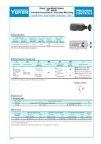
Direct Type Relief Valves DT / DG-02 Threaded Connections / Sub-plate Mounting Specifications / Model Number Designation / others PRESSURE CONTROLS Specifications Model Numbers Threaded Sub-plate Connections Mounting Approx. Mass kg (lbs.) DT type DG type Note: Refer to the Model Number Designation. Model Number Designation FD Special Seals F: Special Seals for Phosphate Ester Type Fluids (Omit if not required) Series Number D: Direct Type Relief Valves Valve Size Design Number Design Standards T: Threaded Connection 02 G: Sub-plate Mounting None: Japanese Std. "JIS" 80: European Design Std....
Open the catalog to page 6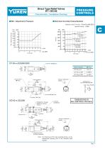
Direct Type Relief Valves DT / DG-02 PRESSURE CONTROLS Characteristics / Installation Drawings Nominal Override Characteristics Hydraulic fluid: Viscosity : 35 mm2/s (164 SSU) Specific Gravity : 0.850 DT-02-∗-2290 Pressure Adjustment Handle Dimensions of The Panel Mounting Hole DIMENSIONS IN MILLIMETRES (INCHES) 5.5(.22) Dia. Through 9(.35) Dia. Spotface 4 Places Pressure Adjustment Handle Mounting Surface (O-Rings Furnished) Note: For dimensions of the valve mounting surface, see the dimensional drawing (P.4) of the sub-plate used together.
Open the catalog to page 7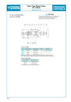
Direct Type Relief Valves DT / DG-02 PRESSURE CONTROLS Spare Parts List DT-02-∗-22/2280/2290 DG-02-∗-22/2290 CAUTION When making replacement of seals, please do it carefully after reading through the relevant instructions in the Operator's Manual. List of Seals Item Part Numbers Note: When ordering the seals, please specify the seal kit number from the table below. List of Seal Kits Model Numbers
Open the catalog to page 8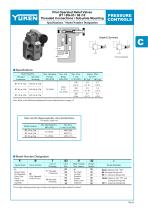
Pilot Operated Relief Valves BT / BG-03 / 06 /10 Threaded Connections / Sub-plate Mounting Specifications / Model Number Designation PRESSURE CONTROLS Graphic Symbols Vent Connection Specifications Model Numbers Threaded Sub-plate Connection Mounting Approx. Mass kg (lbs.) BT type BG type Note: Refer to the Minimum adjustment Pressure characteristics on page 14. Yuken can offer flanged connection valves described below. For details, contact us. Model Numbers Model Number Designation FSpecial Seals F: Special Seals for Phosphate Ester Type Fluids (Omit if not required) Series Number Valve Size...
Open the catalog to page 9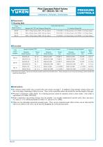
Pilot Operated Relief Valves BT / BG-03 / 06 / 10 Attachment / Sub-plate / Instructions PRESSURE CONTROLS Attachment Mounting Bolts Socket Head Cap Screw Valve Model Numbers Japanese Std. "JIS" and European Design Std. Sub-plate Valve Model Numbers BG-03 Japanese Standard "JIS" Sub-plate Model Numbers Thread Size European Design Standard Sub-plate Model Numbers Thread Size N. American Design Standard Sub-plate Model Numbers Thread Size Sub-plates are available. Specify the sub-plate model number from the table above. When sub-plates are not used, the mounting surface should have a good ma-chined...
Open the catalog to page 10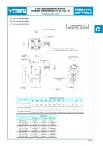
Pilot Operated Relief Valves Threaded Connections:BT-03 / 06 / 10 PRESSURE CONTROLS DIMENSIONS IN MILLIMETRES (INCHES) Lock Nut 14(.55) Hex. 4 positions of pressure adjustment handle are available by rotating cover assembly as shown. Pressure Adjustment Handle 5 (.20) Vent Port "T" Thd. 3280 Design Only Pressure Port "S" Thd. 2 Places T Pressure Gauge Connection "U" Thd. Rc 3/8 3/8 BSP.F 3/8 NPT Rc 3/4 3/4 BSP.F 3/4 NPT Rc 1-1/4 1-1/4 BSP.F 1-1/4 NPT Rc 3/8 3/8 BSP.F 3/8 NPT Rc 3/8 3/8 BSP.F 3/8 NPT Rc 3/8 3/8 BSP.F 3/8 NPT Rc 1/4 1/4 BSP.Tr 1/4 NPT Rc 1/4 1/4 BSP.Tr 1/4 NPT Rc 1/4 1/4 BSP.Tr...
Open the catalog to page 11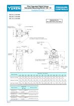
Pilot Operated Relief Valves Sub-plate Mounting:BG-03 / 06 / 10 PRESSURE CONTROLS MENSIONS IN MILLIMETRES (INCHES) Mounting Surface (O-Rings Furnished) 3 positions of pressure adjustment handle are available by rotating cover assembly as shown. Pressure Adjustment Handle INC. Fully Extended C Pressure Gauge Connection "X" Thd. In case of BG-03, no spotface are made at those two holes. Model Numbers "S" Dia. Through "T" Dia. Spotface 4 Places Thread Size "X" Thd Rc 1/4 = 1/4 BSP.Tr 1/4 NPT Rc 1/4 = 1/4 BSP.Tr 1/4 NPT Rc 1/4 = 1/4 BSP.Tr 1/4 NPT Mounting Surface
Open the catalog to page 12All YUKEN Europe Ltd. catalogs and technical brochures
 DP SJT
1 Page
 BUCG
BUCG6 Pages
 BG BT
BG BT7 Pages
 DT-02, DG-02 series
3 Pages
 ASE series
4 Pages
 Flow Control Valve
1 Page
 A3HG Piston Pump
2 Pages
 "A" Series Piston Pumps
20 Pages
 SERVO VALVES
3 Pages
 Throttle (& Check) Modules
7 Pages
 Unloading Relief Valve
7 Pages
 04 Modular
8 Pages
 A7H Pump
8 Pages
 VANE PUMPS
4 Pages
 PVR series
1 Page
 Linear Servo Valve
15 Pages
 Modular Valves
1 Page
 Pressure Control Valves
1 Page
 Linear Servo Valve
15 Pages
 "PV2R" SERIES
32 Pages
 "A" SERIES PISTON PUMPS
92 Pages


Archived catalogs
 Yuken General Catalogue
1765 Pages