- Catalogs
- YUKEN Europe Ltd.
- Multifunction Slope Controllers
Multifunction Slope Controllers
1 /4Pages

Multifunction Slope Controllers
1 /4Pages
Catalog excerpts
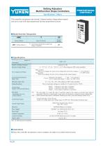
Setting Adjusters Multifunction Slope Controllers PROPORTIONAL CONTROLS Specifications / Others This controller can generate any desired 2-channel analog voltage pattern outputs and can be used with slope-proportional and time-proportional systems. Model Number Designation Series Number Design Number T : Acceleration/deceleration signal type (Slope Controller) Description Number of Output Channels Maximum Output Range 0 - +5 V , 0 - ±5 V, 0 - +10 V, 0 - ±10 V (The settings are DIP switch selectable) Slope-constant With a level change, the slope will not change (but arrival time changes.) Time-constant With a level change, the time will not change (but the slope changes.) Acceleration/Deceleration Signal Type : 1 Type 4 Types Polygonal Line Signal Curve Compensation Signal : 3 Types Maximum Slope Time The level and slope settings are variable in 0.1% units from 0 to ±99.9% Mode 1, 4-bit binary code input, 15 patterns Mode 2, 6-bit binary code input, 63 patterns Mode 3, Timer control, 9 patterns (4 variations) Control Mode Number of Preselected Patterns Control Input Signal Control Output Signal Data Save Power Supply Power Input Ambient Temperature Ambient Humidity Approx. Mass Note: 5 s , 20 s, 50 s, 100 s (The settings are DIP switch selectable) Setting Resolution Stop Mode Applicable Only for Control Mode 1 : The stop mode is to retain the state of controller output at the instant an external input signal is interrupted. When the external signal is input again, the operation is resumed from the retained state. OFF : When external input signal is interrupted, function goes back to the initial setting (Pattern No.0). Current input type, 10 mA /bit max. Usable as a voltage input type (voltage range: 8 to 48V DC) Photocoupler insulation input Output from transister open collector Max. 30V, 50 mA EEP-ROM (Battery not needed) 100/200 V AC, 50/60 Hz (85-260 V AC) Less than 10 VA 0-50°C (32-122°F) Less than 85%RH (Bedewing must be avoided) 1 kg (2.2 lbs.) Indicates preset conditions. Instructions Since this controller incorporates a micro computer, do subject it to undue electrical noise.
Open the catalog to page 1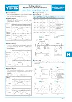
Setting Adjusters Multifunction Slope Controllers PROPORTIONAL CONTROLS Control Modes / Setting Example / Slope Type Control Modes Setting Example One among the following 3 types of control modes can be chosen by changing DIP swicth. Code Input Pattern Setting % No. Level Slope Cylinder forward acceleration Cylinder backward acceleration Cylinder forward deceleration Control Mode 1 Channels A and B generate optional slopes independently each other. Channel-A Code Input Output Channel-B Code Input Control Mode 2 A slope is generated by a strobe signal (signal for change to next signal). Channels...
Open the catalog to page 2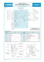
Setting Adjusters Multifunction Slope Controllers PROPORTIONAL CONTROLS Installation Drawing AMC-T Isolation Power Supply DIMENSIONS IN MILLIMETRES (INCHES) Terminal Board Name A out COM B out A1 A2 A4 A8 B1 B2 B4 Channel A Output Common Channel B Output Code Input Code Input Code Input Code Input Code Input Code Input Code Input D : Slope Display M: Channel B Output Indicator Lamp D : Time Display DIP switch D : Alteration of Level Slope Time Values Panel Operating Key Data Set (D) Monitor (M) 70 (2.76) 80 (3.15) Power Supply D : Level Display M: Channel A Output Code Input Code Input Common...
Open the catalog to page 3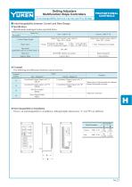
Setting Adjusters Multifunction Slope Controllers Interchangeability between Current and New Design PROPORTIONAL CONTROLS Interchangeability between Current and New Design Specifications Specifications unchanged unless specified below. Model No. Output from transister open collector Max. 30 V, 50 mA Output from transister open collector Max. 30 V, 10 mA Description Control Output Signal : 1 Type 4 Types Polygonal Line Signal Curve Compensation Signal : 3 Types Slope Types 1 Type : Polygonal Line Signal Stop Mode (Applicable only for Control Mode 1) Data Save EEP-ROM Battery not needed Battery...
Open the catalog to page 4All YUKEN Europe Ltd. catalogs and technical brochures
 DP SJT
1 Page
 BUCG
BUCG6 Pages
 BG BT
BG BT7 Pages
 DT-02, DG-02 series
3 Pages
 ASE series
4 Pages
 Flow Control Valve
1 Page
 A3HG Piston Pump
2 Pages
 "A" Series Piston Pumps
20 Pages
 SERVO VALVES
3 Pages
 Throttle (& Check) Modules
7 Pages
 Unloading Relief Valve
7 Pages
 04 Modular
8 Pages
 A7H Pump
8 Pages
 RELIEF VALVES
37 Pages
 VANE PUMPS
4 Pages
 PVR series
1 Page
 Linear Servo Valve
15 Pages
 Modular Valves
1 Page
 Pressure Control Valves
1 Page
 Linear Servo Valve
15 Pages
 "PV2R" SERIES
32 Pages
 "A" SERIES PISTON PUMPS
92 Pages


Archived catalogs
 Yuken General Catalogue
1765 Pages