- Catalogs
- YUKEN Europe Ltd.
- FLOW CONTROL AND RELIEF VALVES
FLOW CONTROL AND RELIEF VALVES
1 /8Pages

FLOW CONTROL AND RELIEF VALVES
1 /8Pages
Catalog excerpts
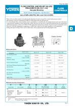
FLOW CONTROL AND RELIEF VALVES FBG-03/06/10 (3/8, 3/4, 1-1/4) Sub-plate Mounting FLOW CONTROLS Model Number Designation / Specifications Up to 25 MPa (3630 PSI), 500 L/min (132 U.S.GPM) These valves are flow control valves having the functions of metre-in type flow control and pressure control. Inlet pressure is always maintained 0.6 MPa (87 PSI) higher than the load pressure. In a conventional flow control method, power consumption is wasteful since the pump pressure goes up to the preset system pressure regardless of the load pressure. While, the power saving valves control the pump pressure by maintaining a differential pressure as little as 0.6 MPa (87 PSI) against the load pressure, thereby, the power can be remarkably saved. Moreover, with lthe temperature compensator, a stable flow control can be made regardless of oil temperature. Setting and repeat setting of flow can be made easily with an adjustment knob having digital scales. Graphic Symbol Specifications Model Numbers Rated Flow Metred Flow Range L /min (U.S.GPM) Pressure Adjustment Range Min. Pressure Difference Required between Inlet 0.6 (87) MPa (PSI) Pilot Drain Flow L /min (U.S.GPM) Max. Drain Line and Tank Line Back Pressure MPa (PSI) Approx. Mass ∗ See the "Min. Adjustment Pressure" for the item marked Model Number Designation FSpecial Seals F: Special Seals for Phosphate Ester Type Fluids (Omit if not required) Series Number Valve Size Max. Metred Flow L /min (U.S.GPM) Design Number Design Standards FB: Flow Control and Relief Valves
Open the catalog to page 1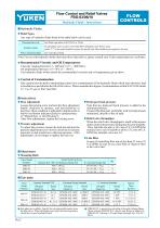
Flow Control and Relief Valves FBG-03/06/10 FLOW CONTROLS Hydraulic Fluids / Instructions Hydraulic Fluids Fluid Types Any type of hydraulic fluids listed in the table below can be used. Petroleum base oils Use fluids equivalent to ISO VG32 or VG46. Use phosphate ester or polyol ester fluid.When phosphate ester fluid is used, prefix "F-" to the model number because the special seals (fluororubber) are required to be used. Synthetic fluids Water containing fluids Note: For use with hydraulic fluids other than those listed above, please consult your Yuken representatives in advance. Recommended...
Open the catalog to page 2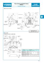
Flow Control and Relief Valves FBG-03 FLOW CONTROLS Flow Adjustment Handle 46(1.81) Dia. INC. Mounting Surface (O-Rings Furnished) 41 (1.61) Drain Port Pressure Adjustment Screw 14(.55) Hex. Controlled Flow Inlet Port Revolution Indicator Controlled Flow Outlet Port 11(.43) Dia. Through 17.5(.69) Dia. Spotface 4 Places Tank Port Vent Port DIMENSIONS IN MILLIMETRES (INCHES) 11(.43) Dia. Through 17.5(.69) Dia. Spotface 4 Places "A" Thd. 3 Places (From Rear) "B" Thd. (From Rear)
Open the catalog to page 3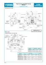
Flow Control and Relief Valves FBG-06 FLOW CONTROLS Revolution Indicator Controlled Flow Inlet Port 20.3 (.80) Locating Pin 16(.63) Dia. 2 Places Mounting Surface (O-Rings Furnished) Flow Adjustment Handle 46(1.81) Dia. INC. 62 (2.44) 17.5(.69) Dia. Through 26(1.02) Dia. Spotface 4 Places Tank Port Pressure Adjustment Screw 14(.55) Hex. INC. Drain Port Controlled Flow Outlet Port Vent Port DIMENSIONS IN MILLIMETRES (INCHES) "E" Thd. (From Rear) 3 Places 6.2(.24) Dia. "H" Thd. (From Rear) D C "J" Thd. "K" Deep 4 Places 17.5(.69) Dia. Through 26(1.02) Dia. Spotface 4 Places
Open the catalog to page 4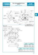
Flow Control and Relief Valves FBG-10 FLOW CONTROLS Revolution Indicator Sling Fitting Screw "M8" Thd. 16(.63) Deep 2 Places Mounting Surface (O-Rings Furnished) Flow Adjustment Handle 46(1.81) Dia. Drain Port Controlled Flow Inlet Port Tank Port Pressure Adjustment Screw 14(.55) Hex. INC. 21.5(.85) Dia. Through 32(1.26) Dia. Spotface 4 Places Vent Port Controlled Flow Outlet Port DIMENSIONS IN MILLIMETRES (INCHES) 48(1.89) Dia. 3 Places (From Rear) "H" Dia. "B" Thd. (From Rear) 21.5(.85) Dia. Through 32(1.26) Dia. Spotface 4 Places 43.5(1.71) Dia. 3 Places "E" Thd. "F" Deep 12 Places (From Rear)...
Open the catalog to page 5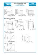
Flow Control and Relief Valves FBG-03/06/10 FLOW CONTROLS Performance Characteristics Min. Adjustment Pressure Flow Rate Flow Rate Flow Rate Load Pressure vs. Metred Flow FBG-03 Metred Flow Metred Flow Load Pressure Metred Flow Load Pressure Load Pressure Metred Flow vs. Dial Position Loading Pressure : 7 MPa(1020 PSI) U.S.GPM 35 Flow Rate Fully Open Dial Position Dial Position U.S.GPM 140 Flow Rate Flow Rate Fully Open Dial Position Fully Open
Open the catalog to page 6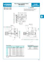
Flow Control and Relief Valves FBG-03/06/10 FLOW CONTROLS Spare Parts List FBG-03-125-10/1090 FBG-06-250-10/1090 FBG-10-500-10/1090 CAUTION When making replacement of seals, please do it carefully after reading through the relevant instructions in the Operator's Manual. List of Seals Item Back Up Ring O-Ring O-Ring O-Ring O-Ring O-Ring O-Ring O-Ring O-Ring O-Ring Note: When ordering the seals, please specify the seal kit number from the table right.
Open the catalog to page 7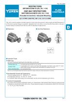
FLOW CONTROLS Threaded Connections / Sub-plate Mounting Up to 25 MPa (3630 PSI), 500 L/min (132 U.S.GPM) This valve is used to regulate an actuator speed in a circuit where line pressure is almost steady and small fluctuation of oil flow due to pressure changes is permitted. Integrated check valve allows reversed free flow from outlet to inlet port. Pressure balanced construction provides less effort in adjustment at high pressure. Hydraulic Fluids Fluid Types Any type of hydraulic fluid listed in the table below can be used. Petroleum base oils Synthetic fluids Water containing fluids Use fluids...
Open the catalog to page 8All YUKEN Europe Ltd. catalogs and technical brochures
 DP SJT
1 Page
 BUCG
BUCG6 Pages
 BG BT
BG BT7 Pages
 DT-02, DG-02 series
3 Pages
 ASE series
4 Pages
 Flow Control Valve
1 Page
 A3HG Piston Pump
2 Pages
 "A" Series Piston Pumps
20 Pages
 SERVO VALVES
3 Pages
 Throttle (& Check) Modules
7 Pages
 Unloading Relief Valve
7 Pages
 04 Modular
8 Pages
 A7H Pump
8 Pages
 RELIEF VALVES
37 Pages
 VANE PUMPS
4 Pages
 PVR series
1 Page
 Linear Servo Valve
15 Pages
 Modular Valves
1 Page
 Pressure Control Valves
1 Page
 Linear Servo Valve
15 Pages
 "PV2R" SERIES
32 Pages
 "A" SERIES PISTON PUMPS
92 Pages


Archived catalogs
 Yuken General Catalogue
1765 Pages
- Lumibird industrial pump
- Lumibird stationary pump
- Lumibird water pump
- Lumibird lubricant pump
- Lumibird oil pump
- Lumibird suction pump
- Lumibird regulating valve
- Lumibird flap valve
- Lumibird electric valve
- Lumibird piston pump
- Directional control valve
- Lumibird food product pump
- Lumibird discharge pump
- Lumibird standard pump
- Standard valve
- Lumibird hydraulic valve