- Catalogs
- YUKEN Europe Ltd.
- Flow Control (& Check) / Pilot Operated Flow Control (& Check) Valves
Flow Control (& Check) / Pilot Operated Flow Control (& Check) Valves

Flow Control (& Check) / Pilot Operated Flow Control (& Check) Valves
Catalog excerpts
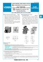
FLOW CONTROL (AND CHECK) VALVES FG FCG -01/02/03/06/10 (1/8,1/4,3/8,3/4,1-1/4) PILOT OPERATED FLOW CONTROL (AND CHECK) VALVES FHG FHCG -02/03/06/10 (1/4,3/8,3/4,1-1/4) Sub-plate Mounting FLOW CONTROLS Hydraulic Fluids Fluid Types Any type of hydraulic fluids listed in the table below can be used. Petroleum base oils Synthetic fluids Water containing fluids Use fluids equivalent to ISO VG 32 or VG 46. Use phosphate ester or polyol ester fluid. When phosphate ester fluid is used, prefix "F-" to the model number because the special seals (fluororubber) are required to be used. Use water-glycol fluid. Note: For use with hydraulic fluids other than those listed above, please consult your Yuken representatives in advance. Recommended Viscosity and Oil Temperatures Viscosity ranging between 15 - 400 mm2/s (77 - 1800 SSU). Oil temperatures between -15/+70°C (5 - 158°F). Use hydraulic fluids which satisfy the recommended viscosity and oil temperatures given above. Control of Contamination Due caution must be paid to maintaining control over contamination of the hydraulic fluids which may otherwise lead to breakdowns and shorten the life of the valves. Please maintain the degree of contamination within NAS 1638Grade 12. Use 25 μ m or finer line filter.
Open the catalog to page 1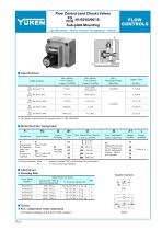
Flow Control (and Check) Valves FG FCG -01/02/03/06/10 Sub-plate Mounting FLOW CONTROLS Specifications / Model Number Designation / Others Specifications Max. Metred Flow Capacity L /min (U.S.GPM) Min. Metred Flow Capacity L /min (U.S.GPM) Model Numbers The figures in the brace are for pressures above 7 MPa (1020 PSI). Model Number Designation Series Number Valve Size Max. Metred Flow Capacity L /min (U.S.GPM) Pres. Compensator Stroke Adjustment Design Number Design Standards N: Applicable only for Pres. Compensator Stroke Adjustment (Option - Omit if not required) FSpecial Seals F: Special Seals...
Open the catalog to page 2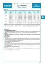
Flow Control (and Check) Valves FG FCG -01/02/03/06/10 FLOW CONTROLS Sub-plate / Instructions Sub-plate Japanese Standard "JIS" Valve Model Numbers Thread Size Thread Size Thread Size 1/4 BSP.F 3/8 BSP.F 1/2 BSP.F 3/8 BSP.F 1/2 BSP.F 3/4 BSP.F 1 BSP.F 1 BSP.F 1-1/4 BSP.F 1-1/2 BSP.F Sub-plates are available. Specify the sub-plate model number from the table above. When sub-plates are not used, the mounting surface should have a good machined finish. FGM-10Y is special type sub-plate to be used with pipe flange. When ordering FGM-10Y, specify pipe flange kit in addition to FGM-10Y referring to...
Open the catalog to page 3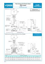
Flow Control (and Check) Valves FG FCG -01/02/03 FLOW CONTROLS Revolution Indicator Locking Screw 2.5(.10) Hex. Soc. Tightening Torque: 0.25 - 0.3 Nm (2.2 - 2.7 IN. lbs.) DIMENSIONS IN MILLIMETRES (INCHES) Controlled Flow Outlet or Reversed Free Flow Inlet Port Flow Adjustment Dial 5.5(.22) Dia. Through 9(.35) Dia. Spotface 4 Places Pressure Compensator Stroke Adjustment (Only for FG -01-∗-N ) FCG Mounting Surface (O-Rings Furnished) Controlled Flow Inlet or Reversed Free Flow Outlet Port Locking Screw 2(.08) Hex. Soc. Controlled Flow Inlet or Reversed Free Flow Outlet Port Pressure Compensator...
Open the catalog to page 4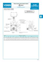
Flow Control (and Check) Valves FG FCG -06/10 FLOW CONTROLS DIMENSIONS IN MILLIMETRES (INCHES) Controlled Flow Inlet or Reversed Free Flow Outlet Port Q Pressure Compensator Stroke Adjustment (Only for FG -∗-∗-N ) FCG H "X" Dia. through "Y" Dia. Spotface 4 Places Mounting Surface (O-Rings Furnished) Controlled Flow Outlet or Reversed Free Flow Inlet Port Z Only for Flow Control and Check Valves ( FCG-∗-∗-N ) Revolution Indicator Flow Adjustment Handle
Open the catalog to page 5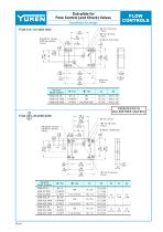
Sub-plate for Flow Control (and Check) Valves FLOW CONTROLS Installation Drawings "A" Thd. (From Rear) 2 Places 5.5(.22) Dia. Through 9(.35) Dia. Spotface 4 Places Sub-plate Model Numbers 8.8(.35) Dia. Through 14(.55) Dia. Spotface 4 Places Sub-plate Model Numbers Rc 1/4 1/4 BSP.F 1/4 NPT Rc 3/8 3/8 BSP.F 3/8 NPT Rc 1/2 1/2 BSP.F 1/2 NPT H "A" Thd. (From Rear) 2 Places
Open the catalog to page 6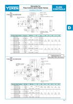
Sub-plate for Flow Control (and Check) Valves FLOW CONTROLS Installation Drawings 03 FGM-03X-20/2080/2090 03Y 03Z "A" Thd. (From Rear) "A" Thd. Rc 3/8 3/8 BSP.F 3/8 NPT Rc 1/2 1/2 BSP.F 1/2 NPT Rc 3/4 3/4 BSP.F 3/4 NPT Rc 1 1 BSP.F 1 NPT 11(.43) Dia. Through 17.5(.69) Dia. Spotface 4 Places DIMENSIONS IN MILLIMETRES (INCHES) "B" Thd. "C" Deep 4 Places 17(.67) Dia. 10(.39) Deep 2 Places 17.5(.69) Dia. Through 26(1.02) Dia. Spotface 4 Places "A" Thd. Rc 1 1 BSP.F 1 NPT Rc 1-1/4 1-1/4 BSP.F 1-1/4 NPT Rc 1-1/2 1-1/2 BSP.F 1-1/2 NPT "A" Thd. (From Rear) 2 Places
Open the catalog to page 7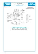
Sub-plate for Flow Control (and Check) Valves FLOW CONTROLS DIMENSIONS IN MILLIMETRES (INCHES) "B" Thd. "D" Deep 8 Places (From Rear) 20(.79) Dia. 15(.59) Deep 2 Places Pipe Flange 21.5(.85) Dia. Through 32(1.26) Dia. Spotface 4 Places 45 (1.77) 25 (.98) Sub-plate Model Numbers FGM-10Y-20 FGM-10Y-2090
Open the catalog to page 8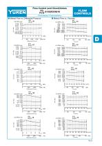
Flow Control (and Check)Valves FG FCG -01/02/03/06/10 FLOW CONTROLS Performance Characteristics Metred Flow vs. Differential Pressure Metred Flow vs. Viscosity Flow Rate Flow Rate Flow Rate Flow Rate Flow Rate Flow Rate Differential Pressure U.S.GPM L/min Flow Rate Flow Rate Flow Rate Flow Rate
Open the catalog to page 9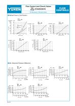
Flow Control (and Check) Valves FG FCG -01/02/03/06/10 FLOW CONTROLS Performance Characteristics Metred Flow vs. Dial Position FG -01 FCG Flow Rate Flow Rate Flow Rate Flow Rate U.S.GPM L/min Min. Required Pressure Difference Differential Pressure Flow Rate Flow Rate Flow Rate Differential Pressure Differential Pressure Differential Pressure Flow Rate
Open the catalog to page 10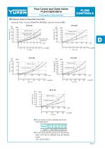
Flow Control and Check Valves FCG-01/02/03/06/10 FLOW CONTROLS Performance Characteristics Pressure Drop for Reversed Free Flow Hydraulic Fluid: Viscosity 35 mm2/s (164 SSU) , Specific Gravity 0.850 FCG-01 Throttle Fully Open (FCG-01-4) Throttle Fully Open (FCG-01-8) Pressure Drop Throttle Closed 0.4 Throttle Fully Open 0.2 Throttle Closed Throttle Fully Open Pressure Drop Throttle Fully Open Throttle Closed Throttle Closed Pressure Drop Pressure Drop Throttle Closed Throttle Fully Open For any other viscosity, multiply the factors in the table below. Viscosity For any other specific gravity...
Open the catalog to page 11All YUKEN Europe Ltd. catalogs and technical brochures
 DP SJT
1 Page
 BUCG
BUCG6 Pages
 BG BT
BG BT7 Pages
 DT-02, DG-02 series
3 Pages
 ASE series
4 Pages
 Flow Control Valve
1 Page
 A3HG Piston Pump
2 Pages
 "A" Series Piston Pumps
20 Pages
 SERVO VALVES
3 Pages
 Throttle (& Check) Modules
7 Pages
 Unloading Relief Valve
7 Pages
 04 Modular
8 Pages
 A7H Pump
8 Pages
 RELIEF VALVES
37 Pages
 VANE PUMPS
4 Pages
 PVR series
1 Page
 Linear Servo Valve
15 Pages
 Modular Valves
1 Page
 Pressure Control Valves
1 Page
 Linear Servo Valve
15 Pages
 "PV2R" SERIES
32 Pages
 "A" SERIES PISTON PUMPS
92 Pages


Archived catalogs
 Yuken General Catalogue
1765 Pages