- Catalogs
- YUKEN Europe Ltd.
- EDFHG-04/06 (Proportional directional and flow control valves)
EDFHG-04/06 (Proportional directional and flow control valves)
1 /4Pages

EDFHG-04/06 (Proportional directional and flow control valves)
1 /4Pages
Catalog excerpts
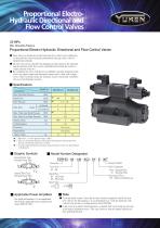
Proportional ElectroHydraulic Directional and Flow Control Valves 25 MPa Max. Operating Pressure Proportional Electro-Hydraulic Directional and Flow Control Valves These valves are double-deck directional and flow control valves employing as their pilot the electro-hydraulic proportional reducing valves with two proportional solenoids. The flow rate can be controlled by changing an input current to the solenoids and the direction of the flow can be controlled by providing the current to either solenoid of the two. By combining the valves with the power amplifiers specially designed for the valves, the speed control and directional control can be done with a single valve, which eventually makes the hydraulic circuits sim ple and contributes the cost of the hydraulic systems. Description Max Operating Pressure Rated Flow Pilot Pressure Pilot Flow Max. Tank Line Back Pressure Max. Drain Line Back Pressure Rated Current Coil Resistance Hysteresis Approx. Mass 1 : Rated flow : At valve pressure drop 1.0 MPa. 2 : Take care to keep the difference between the pilot pressure and drain port back pressure consistently greater than 1.5 MPa. 3 : To obtain staple performance, keep the drain port back p ressure low and minimize its fluctuations. Graphic Symbols Model Number Designation External Pilot Type External Drain Type A Internal Pilot Type External Drain Type A Design Number Pilot Connection None : Internal Pilot E : External Pilot Direction of Flow : XY : Meter-in & Meter-out Rated Flow 04 : 140 L/min 06 : 280 L/min Spool Type 3C2 Applicable Power Amplifiers For stable performance, it is recommended that Yuken's applicable power amplifiers be used (AMN-W-10T) To ensure stable control , bleed the air from solenoid completely and fill the iron core with oil. For this purpose, it is recommended to pr ovide the drain line with a check valve having a cracking pressure about 0.04 MPa. In the event of an electric fault emergency, a manual shift can be made by screwing in the manual adjustment screw. Take care, however, that this manual shift has no flow adjusting function. Mounting Bolts. (Attachment) M ( 1.2 ~ 1.5 )
Open the catalog to page 1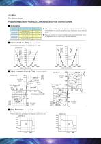
Proportional Electro-Hydraulic Directional and Flow Control Valves Sub-plates Sub-plate Model No. Sub-plate are available, specify the sub-plate model no from the table above, when sub-plates are used, the mounting surface should have a good machined finish . Thread Size Input current vs. Flow Valve Pressure Difference : P Sub-plates are those for solenoid controlled pilot operated directional valves, for dimensions, refer to DSHG series sub-plate dimensions. Flow Rate 80 L/min Valve Pressure Drop vs. Flow Valve Pressure Diff. MPa Valve Pressure Diff. MPa Flow Rate L/min 280 240 Valve Pressure...
Open the catalog to page 2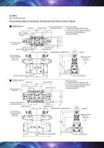
Proportional Electro-Hydraulic Directional and Flow Control Valves EDFHG-04- ( For External Pilt Models Only ) Pilot Pressure Port "X" Mounting Surface : Comfort to ISO 4401-AD-07-4-A-80 For valve mounting surface dimensions , see the dimensional drawings of sub-plates DSHG-04 Dia. 11 Through Dia. 17.5 Spotface 4 Places Air Vent (Both Ends) 3 Hex. Soc. Cylinder Port "A" Pilot Drain Port "Y" Dia. 7 Through ; Dia. 11 Spotface 2 Places Cylinder Port "B" Cable Departure ( Outside Dia. 8-10 ) Use for changing the air vent direction ( Both Ends ) Mounting surface ( O-rings furnished ) Pilot Drain Port...
Open the catalog to page 3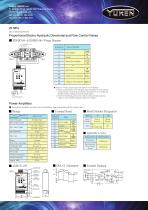
YUKEN EUROPE Ltd 51 Spindus Road, Speke Hall Industrial Estate Liverpool, UK, L24 1YA Tel: +44 (0)151 486 4696 Fax: +44 (0)151 486 3537 Proportional Electro-Hydraulic Directional and Flow Control Valves EDFHG-04- & EDFHG-06- Wiring Diagram Cable Departure Cable Applicable: outside Dia. 8-10mm Conductor Area ( 0.75~1.5mm 2 ) Power Supply Internal Power Supply Input Signal SPANa SPANb DELAY Output to Valve Solenoid POWER MODEL Attention : Wiring of Input signal and output to valve solenoid : 1. Please use the isolation wire with input signal and output to valve solenoid and the ground wire must...
Open the catalog to page 4All YUKEN Europe Ltd. catalogs and technical brochures
 DP SJT
1 Page
 BUCG
BUCG6 Pages
 BG BT
BG BT7 Pages
 DT-02, DG-02 series
3 Pages
 ASE series
4 Pages
 Flow Control Valve
1 Page
 A3HG Piston Pump
2 Pages
 "A" Series Piston Pumps
20 Pages
 SERVO VALVES
3 Pages
 Throttle (& Check) Modules
7 Pages
 Unloading Relief Valve
7 Pages
 04 Modular
8 Pages
 A7H Pump
8 Pages
 RELIEF VALVES
37 Pages
 VANE PUMPS
4 Pages
 PVR series
1 Page
 Linear Servo Valve
15 Pages
 Modular Valves
1 Page
 Pressure Control Valves
1 Page
 Linear Servo Valve
15 Pages
 "PV2R" SERIES
32 Pages
 "A" SERIES PISTON PUMPS
92 Pages


Archived catalogs
 Yuken General Catalogue
1765 Pages