BUCG
1 /6Pages

BUCG
1 /6Pages
Catalog excerpts

PRESSURE CONTROLS These valves are used to operate the pumps with minimum load in accumulator circuits or in high-low pump circuits. In accumulator circuits, when the system pressure reaches to a cut out pressure (adjusted maximum), the valve acts to divert the pump delivery to the reservoir at low pressure, thus the pump is unloaded automatically. When the accumulator pressure drops to the cut in pressure (refer to characteristic chart on page 269), the valve directs the pump delivery to the accumulator and hydraulic system. An integral check valve prevents reverse flow through the valve from the accumulator. In high-low pump circuits, the valve acts to unload the large volume pump with the same manner as described above during load operation of the small volume pump. Model Numbers ■ Model Number Designation Unloading Relif Valves ★ Use the high-venting-pressure type to reduce the shift time from unloading to onloading. Graphic Symbol • Pilot-drain system A pilot-drain system is typically configured with an external pilot and an external drain, as indicated by the right graphic symbol. However, customized pilot-drain systems with an internal pilot are also available. For the internal pilot type, the design standard number at the end of the model number is uniquely assigned. Refer to the table below for the internal pilot type. Please contact us for details. Unloading Relief Valves
Open the catalog to page 1
■ Instructions • To adjust the pressure, loosen the lock nut and turn the pressure adjustment handle slowly clockwise for higher pressures or anti-clockwise for lower pressures. After adjustments, do not forget to tighten the lock nut. • Take care not to neglect connecting the drain pipe to the reservoir; otherwise not only will the valve fail to operate properly but also the line pressure will rise infinitely. Extend the end of the drain pipe into fluid. • Limit the pressure drop between the valve and the accumulator in an accumulator circuit below 10% of the cut-out pressure. • Limit the drain...
Open the catalog to page 2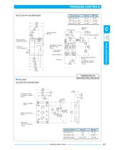
Model Numbers Drain Port Mounting Surface (O-Rings Furnished) 14(.55) Hex. Pressure Adjustment Handlle n INC. DIMENSIONS IN MILLIMETRES (INCHES) ■ Sub-plate BUCGM-06-20/2080/2090 Sub-plate Model No. Unloading Relief Valves
Open the catalog to page 3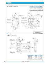
■ Sub-plate BUCGM-10-20/2080/2090 DIMENSIONS IN MILLIMETRES (INCHES) Unloading Relief Valves
Open the catalog to page 4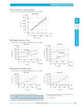
■ Cut-in Pressure vs. Cut-out Pressure Hydraulic Fluid: Viscosity 35 mm2/s (164 SSU), Specific Gravity 0.850 Hydraulic Fluid: Viscosity 35 mmz/s (164 SSU), Specific Gravity 0.850 I Pressure Drop for Check Valve Hydraulic Fluid: Viscosity 35 mmz/s (164 SSU), Specific Gravity 0.850 BUCG-06 PSI MPa • For any other viscosity, multiply the factors in the table below. • For any other specific gravity (G'), the pressure drop (JP’) may be obtained from the formula below. JP’=JP (G70.850) Unloading Relief Valves
Open the catalog to page 5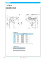
■ Spare Parts ListBUCG-06-* *-30/3080/3090 BUCG-10-* *-25/2580/2590 • List of Seals Unloading Relief Valves
Open the catalog to page 6All YUKEN Europe Ltd. catalogs and technical brochures
 DP SJT
1 Page
 BG BT
BG BT7 Pages
 DT-02, DG-02 series
3 Pages
 ASE series
4 Pages
 Flow Control Valve
1 Page
 A3HG Piston Pump
2 Pages
 "A" Series Piston Pumps
20 Pages
 SERVO VALVES
3 Pages
 Throttle (& Check) Modules
7 Pages
 Unloading Relief Valve
7 Pages
 04 Modular
8 Pages
 A7H Pump
8 Pages
 RELIEF VALVES
37 Pages
 VANE PUMPS
4 Pages
 PVR series
1 Page
 Linear Servo Valve
15 Pages
 Modular Valves
1 Page
 Pressure Control Valves
1 Page
 Linear Servo Valve
15 Pages
 "PV2R" SERIES
32 Pages
 "A" SERIES PISTON PUMPS
92 Pages


Archived catalogs
 Yuken General Catalogue
1765 Pages