- Catalogs
- YOKOGAWA Europe
- YS1500
- Products
- Catalogs
- News & Trends
- Exhibitions
YS1500
1 /20Pages

YS1500
1 /20Pages
Catalog excerpts

General Specifications l tiona Func ment nce Enha n GENERAL The YS1500 Indicating Controller incorporates fundamental control functions required for PID control. Necessary functions can be selected in accordance with the user’s purpose. The available functions include those functions necessary for input signal processing, such as square root extraction and linear segment conversion, and feed-forward calculation. Single-loop, cascade and selector mode is also available. Standard models are smaller and lighter than earlier series, requiring less space for installation, and are compliant with international safety standards including the CE Mark and FM, CSA nonincendive (optional) approvals. For easy replacement of earlier controllers, models requiring the same panel cutout dimensions and depth as those of earlier models are also offered. • 250 mm depth (for basic types only) • Dust- and splash-proof IP54 faceplate (for basic type only) • CE Mark (for basic type and YS100 compliant type only) • FM Nonincendive explosion protection (optional for basic type only) • CSA Nonincendive explosion protection (optional for basic type). • Communication (optional) - Ethernet (Modbus/TCP; for basic type only) - RS485 (PC Link, Modbus and YS protocol; unavailable for YS80 internal unit-compatible type) - DCS-LCS communication • Compatibility with YS100 Series: Setting and control operations can be done with the same feel. For basic-type cases, terminal-to-terminal pitches differ but the signal-to-terminal arrangement is almost the same. • Excellent legibility thanks to a full-dot, TFT LCD: High visibility of the display screen is ensured even in direct sunlight in the early morning and late afternoon. The user can freely access a desired operation display from meter, trend display, bar graph, alarm, and event displays. All parameters can be set via the front panel display. • Function selection mode (needs no programming): The multi-function controller mode allows control to be selected from frequently used functions (single-loop, cascade, or selector control) without programming. Function assignments to digital and analog inputs/outputs (DIs, DOs, AIs, and AOs) can be determined by parameter settings. • Fail-safe: Thanks to dual CPU (one for control and one for display), display and manual operations are enabled even during a failure of either CPU. The hard manual circuit incorporated independently from the digital circuits enables the controller output to be adjusted manually during a failure of a digital circuit including both CPUs. (The hard manual circuit is not incorporated when the suffix code -2xx option is specified.) • Nonvolatile memory for memory backup: No battery or capacitor is used for memory backup, facilitating maintenance. • AC/DC dual power supply with wide operating voltage range to ensure stability against supply voltage fluctuations: Can be driven by either an AC (100 V) or DC (24 V) power supply. Furthermore, the DC power supply enables receiving power without polarity. (Must be specified upon ordering if using a 220 V AC power supply.) Type Basic type Model and Suffix Codes (x: Depending on specifications) YS1500-x0x Digital Inputs and Outputs (*1) 6 Analog Inputs Direct inputs (*2) Compatible type for YS80 internal unit Compatible type for EK and HOMAC Compatible type for YS80( Compatible YS1500-x4x (/Ax) 4 (3) (1) 2 size for YS80 with YS100 terminal) Compatible type for 100 line( with YS1500-x5x (/Ax) 4 (3) (1) 2 YS100 terminal) *1: Each can be used as either a DI or DO by a parameter setting. *2: One from among four analog inputs can be used for a direct input (Option/Ax where x = 01 to 08). Yokogawa Electric Corporation 2-9-32, Nakacho, Musashino-shi, Tokyo, 180-8750 Japan
Open the catalog to page 1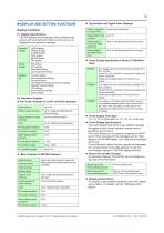
2 n DISPLAY AND SETTING FUNCTIONS Display Functions (1) Display Specifications YS1500 displays are composed of the following three groups and the individual functions can be set up via displays for the respective settings: Operation displays LOOP displays TREND displays ALARM displays DUAL display METER display FAIL display Tuning displays PID settings STC settings Parameter settings Input/output data display Function settings Input specification settings Password setting Line-segment characterizer function settings Operation display settings LCD settings Communication settings DI/DO settings...
Open the catalog to page 2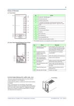
3 Names of Elements (1) Front Panel ⑫ C (cascade), A (automatic), and M (manual) mode keys with respective mode indicators (green LED for C, green for A, yellow for M) Tag label (advisable position to paste) *1 The backlight brightness can be adjusted, and the backlight can be turned off. (2) Inner Panel behind Swing-up Front Panel No. Computer link connector (PROGRAMMER): Communication cable connector used when downloading, uploading, and viewing the parameters using the YSS1000 Setting Software for YS1000 Series Connector for YS110 standby manual station (MANUAL STA) For connecting the YS110...
Open the catalog to page 3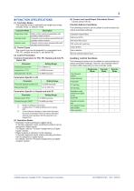
(1) Controller Modes The controller mode is selected from single-loop mode, cascade mode, or selector mode. Controller Mode Single-loop mode Cascade mode Selector mode Description Basic control module preassembled with auxiliary control functions Cascade control module preassembled with auxiliary control functions Selector control module preassembled with auxiliary control functions (2) Control Types The control type can be selected by a parameter from PID, PD, sample-and-hold PI, and batch PID. (3) Control Parameters Common Parameters for PID, PD, Sample-and-hold PI, Batch PID Parameter Setting...
Open the catalog to page 4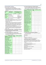
5 Communication Functions Communication with Host Systems Communication with various host systems including Yokogawa’s DCSs such as the CENTUM CS 3000 and programmable logic controllers such as the FA-M3, is supported. Host System Link Device in Host System YS1500 Communication Functions Option Protocol CENTUM CS ALR121 (direct 3000 or VP connection) FA-M3 UT link module PLC or PC from other vendors Modbus RTU/ ASCII (Slave) Modbus/TCP (Server) Ethernet connection Ethernet (/A34) • Communication capabilities: Read access to various measured values, and read and write access to various parameters...
Open the catalog to page 5All YOKOGAWA Europe catalogs and technical brochures
 UM33A/S006
2 Pages
 YTA610
20 Pages
 FA-M3V
19 Pages
 RAMC
RAMC24 Pages
 GS610 Source Measure Unit
12 Pages
 EJXC40A Digital Remote Sensor
135 Pages
 TB750G EXAxt
3 Pages
 VPSRemote Remote Solution
2 Pages
 SENCOM Degital Sensor
3 Pages
 Product Solution Catalog
8 Pages
 Data Logging Software GA10
4 Pages
 JUXTA VJ series
7 Pages
 µR10000/µR20000
8 Pages
 OX400
OX4002 Pages
 PR300 Power and Energy Meter
4 Pages
 CENTUM RIO System Upgrade
4 Pages
 Autonomous Controller FCN-RTU
17 Pages
 MW100
MW1005 Pages
 FieldMate
5 Pages
 AMADAS
4 Pages
 Exapilot
5 Pages
 Exaquantum
5 Pages
 BUCA150_E_050
4 Pages
 BUAQ7280-01
12 Pages
 BUXL120_E_030
8 Pages
 BU7603_00E_060
20 Pages
 BUAQ2200
8 Pages
 NR800 Near Infrared Analyzer
8 Pages
 GD402 Gas Density Analyzer
3 Pages
 DT450G Dust Monitor
3 Pages
 SCADA Software VDS
7 Pages
 Batch Control
9 Pages
 FieldMate catalogs
5 Pages
 DPharp for The Digital World
9 Pages
 RAGN Rotameter
2 Pages
 HART Communicator YHC5150X
2 Pages
 Catalog_YMI130_EN
86 Pages
 Bulletin11G04G01-01E
3 Pages
 Bulletin11B03A03-01E
10 Pages
 FY01A08A08-E-E
2 Pages
 Ultrasonic Flowmeter US300FM
2 Pages
 AXF Verification Tool
2 Pages
 ADMAG Series
9 Pages
 Exaplog
2 Pages
 AAASuite
2 Pages
 InfoWell
8 Pages
 Low Power Controller FCN-RTU
3 Pages
 Standalone SIS
3 Pages
 VTSPortal
2 Pages
 CENTUM VP - CAMS for HIS
4 Pages
 GS01E06K02-00E
2 Pages
 U33Q01A01-01E
11 Pages
 BU33K01A01-50E
11 Pages
 Thermometers Catalog
8 Pages
 PH400G 4-Wire Type pH Meter
27 Pages
 SG750 Stack Gas Analyzers
26 Pages
 Clamp-on Testers
12 Pages
 Dust Monitor DT450G
3 Pages
 Handy Calibrators
4 Pages
 CENTUM.VP
11 Pages
 Fieldbus Segment Indicator
5 Pages
 ADMAG AXF
2 Pages
 YTA series
7 Pages
 TEST & mEASUREmENT 2011
28 Pages
 digital multimeter series
12 Pages
 WT 3000 Precision Power Analyzer
19 Pages
 DL850/DL850V SCOPECORDER
14 Pages


![ADMAG AXR Two-wire Magnetic Flowmeters [Type B]](https://img.directindustry.com/pdf/repository_di/19033/admag-axr-two-wire-magnetic-flowmeters-type-b-569006_1mg.jpg)
![ADMAG AXR Two-wire Magnetic Flowmeters [Type A]](https://img.directindustry.com/pdf/repository_di/19033/admag-axr-two-wire-magnetic-flowmeters-type-569005_1mg.jpg)


Archived catalogs


- AMOT flow meter
- AMOT volume flow meter
- AMOT liquid flow meter
- AMOT transformer
- Ethernet switch
- Gas analyzer
- AMOT management software
- AMOT automation software
- Concentration analyzer
- AMOT dry transformer
- AMOT surge arrester
- Industrial network switch
- AMOT analysis software
- Pressure transmitter
- Liquids analyzer
- AMOT process software
- AMOT Windows software
- AMOT automatic analyzer
- AMOT real-time software
- AMOT cloud software