- Catalogs
- YOKOGAWA Europe
- GS610 Source Measure Unit
- Products
- Catalogs
- News & Trends
- Exhibitions
GS610 Source Measure Unit
1 /12Pages

GS610 Source Measure Unit
1 /12Pages
Catalog excerpts

GS61(|Source Measure Unit H ■ Basic accuracy: 0.02% ■ Wide output range: 110 V, 3.2 A ■ High speed source capability : 100li s/point ■ Arbitrary Waveform Function ■ Curve Tracer Function ■ USB storage function ■ Web Server (Ethernet option) ■ Application Examples • Measurement of basic electrical characteristics of semiconductor devices • Supply voltage fluctuation test of portable or in-vehicle devices • Pulse current drive for LED and organic EL • Charge/Discharge characteristics test of batteries • Power conversion efficiency measurement of DC-DC converters • Pass/Fail judgment test for resistors, thermistors, varistors, etc.
Open the catalog to page 1
Source Measure Unit GS610 Combines YOKOGAWA's DC technologies and consolidates Combines YOKOGAWA's DC technologies and consolidates high accuracy and high speed in a single unit high accuracy and high speed in a single unit The GS610 is a highly accurate and highly functional programmable voltage/current source that incorporates voltage/current generation and measurement functions. The maximum output voltage and current are 110 V and 3.2 A, respectively. Evaluation of over a wide range of basic electrical characteristics is possible, because the GS610 can operate as a current source or a current...
Open the catalog to page 2
Functions Voltage/Current Generation and Measurement Range Four-dimensional operation with source operation (current source) and sink operation (current sink) is possible at up to 110 V, 3.2 A, and 60 W. The output and measurement resolutions are 5.5 digits. Voltage generation/measurement range: 200 mV to 110 V Current generation/measurement range: 20 µA to 3.2 A Maximum output current: ±3.2 A (at an output voltage of ±12 V or less) ±2 A (at an output voltage of ±30 V or less) ±1 A (at an output voltage of ±60 V or less) ±0.5 A (at an output voltage of ±110 V or less) Generation and Measurement...
Open the catalog to page 3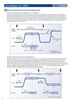
Source Measure Unit GS610 Generation and Measurement Timing (Source Measure Cycle) Source measure cycle (source & measure at 1 ms minimum) As shown in the figure below, the GS610 is capable of synchronizing the generation and measurement at any operation mode. Generation is started after a source delay with respect to an internal/external trigger. Then, after the time it takes for the source level to stabilize (measure delay) the measurement is carried out over a given integration time. This function is necessary when making measurements by waiting for the load response after applying a pulse....
Open the catalog to page 4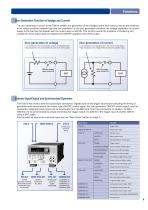
Zero Generation Function of Voltage and Current The zero generation function of the GS610 enables the generation of the voltage/current zero value as well as the switching of the output condition between high and low impedance. In the zero generation condition, the voltage application or current supply to the load can be stopped with the output relay turned ON. This function avoids the problems of chattering and contact life of the output relay and reduces the ON/OFF operation time of the output. Zero generation of voltage • Low impedance: The current limiter is set to the specified value. •...
Open the catalog to page 5
Source Measure Unit GS610 Curve Tracer Function using USB Storage When the GS610 Source Measure Unit is connected to a PC via the USB, the PC detects the GS610 internal memory as a USB storage device. A pattern file can easily be stored in the GS610 internal memory by creating the GS610 generation pattern on a general-purpose worksheet application (1) and dragging and dropping the pattern file (2). The GS610 sweeps the voltage or current levels according to the generation pattern that is written in this file, measures the load current or load voltage at the appropriate points (3), and stores...
Open the catalog to page 6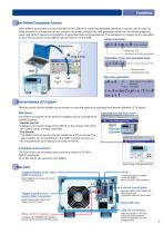
Functions User-Defined Computation Function User-defined computation can be performed on the GS610 by combining dedicated operators. It can be used to carry out linear conversion of measured values, compute the power, compute the next generated value from the current measured value, and perform real-time computation of generated data using expressions. The expression is created using a text editor on your PC and stored to the GS610 internal memory via the USB. Linear conversion Expression file Measured value Measured value after computation Drag & Drop Calculation of the next generated value...
Open the catalog to page 7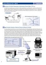
Source Measure Unit GS610 Measurement of the Static Characteristics of Semiconductor Devices (Diode, Tr, FET, etc.) Two GS610s are operated in sync to measure the static characteristics of a transistor. Then, constant h is determined from the slope of each characteristics data. In the IB-IC characteristics measurement, a GS610 for base current IB output and a GS610 for collector current IC measurement are operated in sync to measure the characteristics. The VCE-IC characteristics measurement is possible using one GS610 by connecting the GS610 between the emitter and the collector, applying VCE,...
Open the catalog to page 8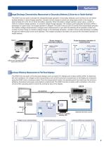
Applications Charge/Discharge Characteristics Measurement of Secondary Batteries (Lithium-Ion or Nickel-Hydride) The GS610 can be used to simulate the charge/discharge operation of secondary batteries such as lithium-ion and nickelhydride batteries. In boost charge operation, constant current charge is carried out using large current in the range of approximately 2C to 5C (2 to 5 times the battery capacity). When the battery voltage reaches a given value, a switch is made to constant voltage operation. In constant voltage charge operation, the charge current gradually decreases. When it decreases...
Open the catalog to page 9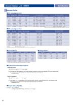
Source Measure Unit GS610neration Section■ DC voltage generation The values inside the parentheses are those when the limiter range is 3 A. ■ DC current generation Accuracy: One year accuracy at 23±5 °C Temperature coefficient: Add the temperature coefficient at 5 to 18 °C and 28 to 40 °C. *1 Larger of the two values |Hi| and |Lo| when |Hi limiter! * ILo limiterl ■ Transient response time (Typical) Voltage generation 100 ps:Time to reach ±0.1% of final value * at 20 V range with the generation and limiter settings at maximum values and under the 25% pure resistive load *1: In condition of zero...
Open the catalog to page 10All YOKOGAWA Europe catalogs and technical brochures
 YS1500
20 Pages
 UM33A/S006
2 Pages
 YTA610
20 Pages
 FA-M3V
19 Pages
 RAMC
RAMC24 Pages
 EJXC40A Digital Remote Sensor
135 Pages
 TB750G EXAxt
3 Pages
 VPSRemote Remote Solution
2 Pages
 SENCOM Degital Sensor
3 Pages
 Product Solution Catalog
8 Pages
 Data Logging Software GA10
4 Pages
 JUXTA VJ series
7 Pages
 µR10000/µR20000
8 Pages
 OX400
OX4002 Pages
 PR300 Power and Energy Meter
4 Pages
 CENTUM RIO System Upgrade
4 Pages
 Autonomous Controller FCN-RTU
17 Pages
 MW100
MW1005 Pages
 FieldMate
5 Pages
 AMADAS
4 Pages
 Exapilot
5 Pages
 Exaquantum
5 Pages
 BUCA150_E_050
4 Pages
 BUAQ7280-01
12 Pages
 BUXL120_E_030
8 Pages
 BU7603_00E_060
20 Pages
 BUAQ2200
8 Pages
 NR800 Near Infrared Analyzer
8 Pages
 GD402 Gas Density Analyzer
3 Pages
 DT450G Dust Monitor
3 Pages
 SCADA Software VDS
7 Pages
 Batch Control
9 Pages
 FieldMate catalogs
5 Pages
 DPharp for The Digital World
9 Pages
 RAGN Rotameter
2 Pages
 HART Communicator YHC5150X
2 Pages
 Catalog_YMI130_EN
86 Pages
 Bulletin11G04G01-01E
3 Pages
 Bulletin11B03A03-01E
10 Pages
 FY01A08A08-E-E
2 Pages
 Ultrasonic Flowmeter US300FM
2 Pages
 AXF Verification Tool
2 Pages
 ADMAG Series
9 Pages
 Exaplog
2 Pages
 AAASuite
2 Pages
 InfoWell
8 Pages
 Low Power Controller FCN-RTU
3 Pages
 Standalone SIS
3 Pages
 VTSPortal
2 Pages
 CENTUM VP - CAMS for HIS
4 Pages
 GS01E06K02-00E
2 Pages
 U33Q01A01-01E
11 Pages
 BU33K01A01-50E
11 Pages
 Thermometers Catalog
8 Pages
 PH400G 4-Wire Type pH Meter
27 Pages
 SG750 Stack Gas Analyzers
26 Pages
 Clamp-on Testers
12 Pages
 Dust Monitor DT450G
3 Pages
 Handy Calibrators
4 Pages
 CENTUM.VP
11 Pages
 Fieldbus Segment Indicator
5 Pages
 ADMAG AXF
2 Pages
 YTA series
7 Pages
 TEST & mEASUREmENT 2011
28 Pages
 digital multimeter series
12 Pages
 WT 3000 Precision Power Analyzer
19 Pages
 DL850/DL850V SCOPECORDER
14 Pages


![ADMAG AXR Two-wire Magnetic Flowmeters [Type B]](https://img.directindustry.com/pdf/repository_di/19033/admag-axr-two-wire-magnetic-flowmeters-type-b-569006_1mg.jpg)
![ADMAG AXR Two-wire Magnetic Flowmeters [Type A]](https://img.directindustry.com/pdf/repository_di/19033/admag-axr-two-wire-magnetic-flowmeters-type-569005_1mg.jpg)


Archived catalogs


- AMOT flow meter
- AMOT volume flow meter
- AMOT liquid flow meter
- AMOT transformer
- Ethernet switch
- Gas analyzer
- AMOT management software
- AMOT automation software
- Concentration analyzer
- AMOT dry transformer
- AMOT surge arrester
- Industrial network switch
- AMOT analysis software
- Pressure transmitter
- Liquids analyzer
- AMOT process software
- AMOT Windows software
- AMOT automatic analyzer
- AMOT real-time software
- AMOT cloud software