
Catalog excerpts
YASKAWA Energy-Saving Unit High-Power Factor Converter with Power Regeneration (Ks=0)
Open the catalog to page 1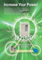
Increase Your Power! You can save more energy with AC drives. The solution is in "power regeneration". Traditionally regenerative energy was discarded as heat, but now the Yaskawa D1000 series of energy-saving units allows you to reuse regenerative energy without wasting it. You saved energy with AC drives, you saved energy with high-efficiency motors, and now you can save energy in a third way, "power regeneration". D1000 makes the most of AC drives to help you save more electricity in your equipm
Open the catalog to page 2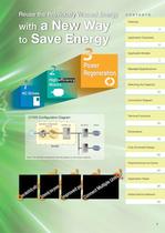
M D1000 unit AC Drive Motor Note: The standard configuration devices depend on the output capacity. Application Examples Applicable Models Standard Specifications Connection Diagram Terminal Functions Fully-Enclosed Design Peripheral Devices and Options Application Notes Global Service Network
Open the catalog to page 3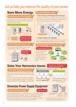
Let us help you improve the quality of your power. Save More Energy Save More Electricity with Power Regeneration Combined with drives or servo systems, D1000 lets you effectively use energy by returning regenerative energy to the power supply. Return Electricity with Power Regeneration Hoisting (drive energy) (regenerative energy) Power supply other devices Regenerative energy Reduce Wasteful Heat Loss You can greatly reduce heat loss from power supply facilities caused by harmonics. Large power supply current distortion rate. Power factor: Approx. 0.7 Small power supply current distortion...
Open the catalog to page 4
Let Us Meet Your Needs Long Life Performance ►The energy-saving unit outputs a signal to the control device indicating components may need to be replaced O Ten Years of Durable Performance Cooling fans, capacitors, and relays have been carefully selected and designed for a life expectancy of up to ten years.* * : Assumes the drive is running continuously for 24 hours a day at 80% load with an ambient temperature of 40°C. Restriction of Hazardous Substances Directive Note: Application pending. O Support for Field Networks RS-422/RS-485 communications capability with the MEMOBUS/Modbus...
Open the catalog to page 5
Conveyance Equipment Cranes, Hoists, and Chain Blocks Improved Power Factor No Power Supply Harmonics Power Regeneration Multiple Drive Connection Stacking Cranes Automated Vertical Storage System Slope Transportation Systems (Monorails and Cable Cars) Automatic Parking System Chemical Plan Weaving Machines Food Processing
Open the catalog to page 6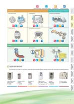
Improved Power Factor No Power Supply Harmonics Power Regeneration Multiple Drive Connection Paper Manufacturing and Printers Cooling Towers Ladle Turrets Machine Tools The following AC drives and AC Servo drives are recommended. Energy-saving units can be connected to existing products. High performance vector control Compact vector High-function Elevator fully vector control applications
Open the catalog to page 7
Standard Specifications Standard Specifications Model CIMR-DAKA;; Max. Applicable Motor Capacity kW Rated Output Capacity" kW Rated Output Current (DC) A Rated Input Current (AC) A Rated Output Voltage Rated Voltage/Rated Frequency Allowable Voltage Fluctuation Allowable Frequency Fluctuation Control Method Input Power Factor Input power factor of 0.99 min. (for rated operation) Output Voltage Accuracy Overload Protection Unit stops after 60 s at 150% of rated output current or after 3 s at 200% of rated output current. Voltage Reference Range Carrier Frequency Main Control Functions...
Open the catalog to page 8
D1000 Standard Configuration Devices Rated Output Environmental Specifications Note: Contact a Yaskawa for more on environmental specifications.
Open the catalog to page 9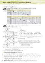
Selecting the Capacity / Connection Diagram The recommended D1000 models are given in the following table when one drive is connected. If more than one drive is connected or for a more detailed selection, use the flowchart to select D1000 capacity. Motor 1 efficiency*1 x Drive 1 efficiency* Motor 1 capacity (kW) Motor 2 capacity (kW) Motor 1 efficiency*1 x Drive 1 efficiency*1 Motor 2 efficiency*1 x Drive 2 efficiency* Motor N efficiency*1 x Drive N efficiency* Total drive capacity*2 (or regenerative capacity*2) (kW) Ps = Pi- (Motor 1 efficiency*1 x Drive 1 efficiency*1 x Motor 1 capacity...
Open the catalog to page 10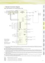
Standard Connection Diagram Option card [Control Circuit] Fault relay output digital inputs [default setting! Shield ground terminal saving unit and standarc configuration devices. shielded line ^twisted-pair shielded line O control circuit termina (5) main circuit termina Modbus comm. Multi-function photocoupler output" Multi-function photocoupler output 2 Termination resistor t>-.-9{~|~fr -^--Vi - - Multi-function analog output 1 :JcS Multi-function analog output 2 *G [Input Current) *1 : When a noise filter is attached on D1000 power supply side, use a noise filter of the reactor type...
Open the catalog to page 11
Connection Diagram (continued) Standard Connection Diagram Fault relay output Multi-function photocoupler output " Multi-function photocoupler output 2 saving unit and standarc configuration devices. ^twisted-pair shielded line O control circuit termina (5) main circuit termina -| Multi-function analog output 2 *G — Multi-function analog output 1 ;[:G Sf^)± -I (Input Voltage) Modbus comm. *1 : When a noise filter is attached on D1000 power supply side, use a noise filter of the reactor type (without a capacitor) such as FINEMET zero-phase reactor. and attach it after the MCCB at the power...
Open the catalog to page 12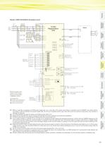
Model: CIMR-DA4A0630 (Available soon) saving unit and standarc configuration devices. zfEj: shielded line ^zj= twisted-pair shielded line O control circuit termina (5) main circuit termina Modbus comm. Shield ground terminal Power supply I Fault relay output Termination resistor Multi-function photocoupler output" Multi-function photocoupler output 2 [Converter Ready) Tf\ —i Multi-function analog output 2 =fcS J L__(AMCL I (Input Current) > |FM c|| j-fp -^V.. - -■ Multi-function analog output 1 *G *1 : When a noise filter is attached on D1000 power supply side, use a noise filter of the...
Open the catalog to page 13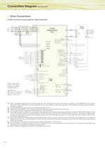
Connection Diagram (continued) Drive Connections A1000 Connection Example (Model: CIMR-DA4A0185) saving unit and standarc configuration devices. shielded line ^zf: twisted-pair shielded line O control circuit termina (§) main circuit termina Modbus comm. Multi-function relay Multi-function analog (Input Current) Multi-function analog (Input Voltage) (Converter Ready) *1 : When a noise filter is attached on D1000 power supply side, use a noise filter of the reactor type (without a capacitor) such as FINEMET zero-phase reactor. and attach it after the MCCB at the power supply side. Do not use...
Open the catalog to page 14Archived catalogs
-
YASKAWA ELECTRIC CORPORATION
10 Pages
-
YASKAWA Report 2012
51 Pages
-
YASKAWA Report 2013
51 Pages
-
YASKAWA Report 2014
55 Pages
-
P1000 Catalog
52 Pages
-
MPiec Machine Controllers
8 Pages
-
YASKAWA HERMETICALLY SEALED CONTACT
110 Pages
-
AC SERVO DRIVES JUNMA SERIES
43 Pages
-
MACHINE CONTROLLER MP2000 SERIES
96 Pages
-
AC SERVO DRIVES
479 Pages
-
YASKAWA AC DRIVES
25 Pages
-
Machine Controller MP920
50 Pages
-
MACHINE CONTROLLER MP2000 SERIES
64 Pages


