AC SERVO DRIVES JUNMA SERIES
1 /43Pages

AC SERVO DRIVES JUNMA SERIES
1 /43Pages
Catalog excerpts
JUNMA SERIES SERVOMOTOR TYPE SJME SERVOPACK TYPE SJDE
Open the catalog to page 1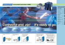
Industry’s First A new concept in servo drives - JUNMA C O N T E N T S In the blink of an eye, a top-level Olympic relay runner passes his baton to his teammate. Not even the smallest motion is wasted. This almost imperceptible speed and accuracy brings their team to victory. JUNMA similarly uses the world’s top-level servo technology to provide a quick and efficient setup. Simply connect the servomotor to JUNMA. That’s all you have to do to obtain stellar servo performance. System Configuration Model Designation 4 JUNMA is a totally new concept in digital servo drives that requires no parameter...
Open the catalog to page 2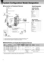
System Configuration/ Model Designation System Configuration/ Model Designation Connection to Peripheral Devices Model Designation Power supply Single-phase 200 VAC SJDE Molded-case circuit breaker *1 JUNMA-series SJDE SERVOPACKs Noise filter SJDE SERVOPACKs Power Supply Voltage A: 200 VAC Surge absorber Interface Specifications P : Pulse-train reference input Magnetic contactor Design Revision Order A CD AB For a servomotor with a holding brake. Upper controller JUNMA-series SJME Servomotors Encoder cable (Junction cable) Power Supply Voltage A : 200 VAC Encoder Specifications M: Incremental...
Open the catalog to page 3
Servomotor Main Circuit Cables with Connectors at Both Ends (Junction Cables) Connector Kits for Servomotor Main Circuit Cable*1 Power Supply and Regenerative Unit Connector Kits*1 Without holding brake With holding brake Yaskawa Local Office Crimp Type Spring Type Crimp Type Yaskawa Local Office Yaskawa Local Office Yaskawa Local Office Spring Type Yaskawa Local Office Yaskawa Local Office Yaskawa Local Office Yaskawa Local Office I/O Signal Cables I/O Signal Connector Kits*1 To Servomotor Plug (For servomotors w/wo holding brake) To SERVOPACK CNB (For servomotors w/wo holding brake) Encoder...
Open the catalog to page 4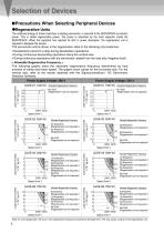
Selection of Devices Selection of Devices Precautions When Selecting Peripheral Devices Regenerative Units The rotational energy of driven machines, including servomotor, is returned to the SERVOPACK as electric power. This is called regenerative power. The power is absorbed by the main capacitor inside the SERVOPACK. When the capacitor has reached its limit in power absorption, the regenerative unit is required to dissipate the excess. The servomotor will be driven in the regeneration state in the following circumstances: • Deceleration period to a stop during deceleration operations. • During...
Open the catalog to page 5
< Caution > • The regenerative unit heats up and reaches a high temperature. Use heat-resistant, non-flammable cables and make sure that the cables do not touch the unit. Refer to P16 for the applicable size of cables to connect the unit. • The regenerative unit has three error detection functions: regenerative resistor disconnection, regenerative transistor fault, and overvoltage detection. When these functions are tripped, the built-in alarm relay will operate and the C1 and C2 output terminals of the regenerative unit will be opened. • The power supply (through L1 and L2) to the SERVOPACK...
Open the catalog to page 6
Motor Connector Specifications 6 Holding brake (de-energization operation) Power supply: 24 VDC With holding brake Phase U Red Phase V White Phase W Blue FG Green/Yellow Brake Red Brake Black PG5V Red 1 Black 2 PG0V(GND) Blue 3 Phase A+ Blue/White 4 Phase A– Yellow 5 Phase B+ 6 Phase B– Yellow/White Phase /Z Purple 7 Phase U Gray 8 Phase V Green 9 Orange 10 Phase W – – 11 FG Shield 12 Without holding brake Red Phase U White Phase V Blue Phase W FG Green/Yellow − − − − Note: Only for servomotors with brakes Holding brake torque = Motor rated torque Plug: 5559-06P-210 Terminal (No.1 to 3, 5, 6):...
Open the catalog to page 8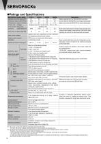
SERVOPACKs SERVOPACKs Ratings and Specifications SERVOPACK model SJDEApplicable servomotor capacity [kW] Continuous output current [Arms] Instantaneous max. output current [Arms] Input power supply Voltage (for main circuit and Frequency Capacity at rated output [kVA] control circuit) Power loss at rated output [W] Input control method Output control method Feedback Allowable load moment of inertia [kgm2]*1 Pulse type Reference input Pulse type or pulse resolution can be selected with the PULSE switch. Clear Servo ON Alarm Pulse resolution Brake Positioning completed Built-in functions Origin...
Open the catalog to page 9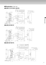
Mounting Hole Diagram Airflow YASKAWA 200V SJDE- 02 APA REF YASKAWA ELECTRIC Ground terminal with 2 × M4 screws (Mounting pitch) Mounting Hole Diagram Visible ovutline YASKAWA ELECTRIC Ground terminal with 2 × M4 screws (Mounting pitch) Mounting Hole Diagram 2-M4 mounting holes 5 Visible outline Ground terminal with 2 × M4 screws YASKAWA ELECTRIC (Mounting pitch)
Open the catalog to page 10
SERVOPACKs SERVOPACKs Part Names and Functions YASKAWA Input voltage Model No. Rotary switch for reference pulse setting (PULSE) Reference indicator (REF) Alarm indicators (AL1 to AL3) Rotary switch for reference filter setting (FIL) Power supply indicator (PWR) Ground terminal Connector for motor main circuit cable (CNB) Connector for power supply / regenerative unit (CNA) Circuit Form Pulse Type Open collector or line driver Positive logic or line driver Line driver Open collector or line driver Line driver Open collector or line driver Line driver CW CCW CW + CCW Negative logic CW CCW Sign...
Open the catalog to page 11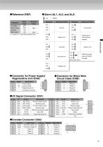
Blinks green : Lit yellow for 1 s when the clear signal is input. Speed error Blinks orange System error Reference pulse setting (PULSE) Encoder error Blinks at regular intervals. Voltage error Connector for Power Supply/ Regenerative Unit (CNA) Signal Name input terminals Regenerative unit connection terminals Signal Name Phase U Phase V Phase W Not used Power supply Connector for Motor Main Circuit Cable (CNB) Signal Name Signal Name Reverse rotation pulse, Position error reference pulse pulse clear Forward rotation pulse, reference sign Phase-C signal Phase-C signal ground External input power...
Open the catalog to page 12
Connection Diagram Connection Diagram Example Power supply Single-phase 200 V to 230 VAC 50/60Hz L1 L2 Molded-case circuit breaker Surge absorber Noise filter Fuse Fuse Holding brake Surge absorber Controller CW,PULS /CW,/PULS Shell Shield Flywheel diode : 24 VDC power supply for holding brake : 24 VDC power supply for I/ O signals : Power off switch : Power on switch : Magnetic contactor : Relay for holding brake *: Prepare separate 24 VDC power supplies for a holding brake and I/ O signals. Manufacturers of Components Flywheel diode Okaya Electric Industries Co., Ltd.(Spark killer): CRE-50500...
Open the catalog to page 13Archived catalogs
 YASKAWA Report 2012
51 Pages
 YASKAWA ELECTRIC CORPORATION
10 Pages
 YASKAWA Report 2013
51 Pages
 YASKAWA Report 2014
55 Pages
 P1000 Catalog
52 Pages
 MPiec Machine Controllers
8 Pages
 YASKAWA HERMETICALLY SEALED CONTACT
110 Pages
 MACHINE CONTROLLER MP2000 SERIES
96 Pages
 AC SERVO DRIVES
479 Pages
 YASKAWA AC DRIVES
25 Pages
 Machine Controller MP920
50 Pages
 MACHINE CONTROLLER MP2000 SERIES
64 Pages


- Yaskawa industrial robot
- Yaskawa articulated robot
- Yaskawa 6-axis robot
- Yaskawa floor-mounted robot
- Yaskawa handling robot
- Servo-amplifier
- AC servo-motor
- Compact robot
- High-speed robot
- 4-axis robot
- Assembly robot
- Ceiling-mounted robot
- DC servo-amplifier
- Applications robot
- Yaskawa AC drive
- Welding robot
- Ultra-compact servomotor
- IP54 robot
- Robot for the food industry