YASNAC 3000G
1 /203Pages

YASNAC 3000G
1 /203Pages
Catalog excerpts

OPERATOR'S MANUAL
Open the catalog to page 1
2. 6. 1 Acceleration and Deceleration of Rapid Traverse
Open the catalog to page 2
2.14.20 Designation of Canned Cycle Return Point (G98, G99)'1' - - ■ 78
Open the catalog to page 3
4.1.10 ERS(Erase), INS (Insert), ALT (Alter), and
Open the catalog to page 4
4. 7.4 Sequence of Tape Data Storing and Punching Operationt . . 114 6. CONTROL STATION FOR MACHINE 126
Open the catalog to page 5
6.1.14 ZERO POSITION Lamps1- (For X, Y, Z, and 4th Axes). . . 130 6. 1.21 M-FUNCTION LOCK Switch 6. 1.24 BLOCK RETURN Switch and 6.1.27 TOOL OFFSET AUTO-STORE Pushbutton and Lampt ... 133 7.4 PREPARATION FOR LEADSCREW ERROR COMPENSATION 7.7 MANUAL OPERATION INTERRUPTING AUTOMATIC OPERATION ■ 142 7.9 MDI OPERATION INTERRUPTING AUTOMATIC OPERATION - - - - 143
Open the catalog to page 6
YASNAC 3000G is a low cost, high performance CNC specifically designed for machining centers to direct a three- or four-motion machine tool. It incorporates the latest microelectronics tech- nology in every design feature, which remarkably upgrades the basic functions and offers a wide variety of optional functions. The improved transistorized PWM servos com- bined with the optimum pulse distribution control provides faster and higher accuracy of machining. The totally-enclosed, dustproof enclosure pro- tects all components from the attack by rugged industrial environment. This contributes to...
Open the catalog to page 8
Table 2.1.1 . Tape Format 1. Functions with t are optional. 2. Only the numbers of digits are shown in the above table. Some of them cannot ex- ceed the maximum programmable value. Refer to the description of each item. 3. Least input increment .(0. 01/0. 001 mm) is parameter-switched. 4. Feedrate is d esignated by either mm (inch) per minute or mm (inch) per revolution, which can be switched by G code. (G94, G95) 6. Inch input is available for the control equipped with an optional Inch/Metric selection. Inch/Metric are parameter-switched. 7. Instead of Deep Hole Drilling Depth Q, addresses I...
Open the catalog to page 9
2.1.2 ADDRESS AND FUNCTION CHARACTERS Address characters and the meanings are shown Function characters and the meanings are shown Table 2.1.2.1 Address Characters
Open the catalog to page 10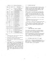
Table 2. 1.2.2 Function Characters 1 . Characters other than the above cause er- ror in significant data area. 2. Information between Control Out and Con- In is ignored as insignificant data. 3. Tape code (EIA or ISO) can be switched by 4. Label Skip function: After switching on the power.supply, or after making RESET op- eration, Label Skip function becomes effec- tive, and LABEL SKIP lamp on the NC op- eration panel lights. In this condition, all tape information is ignored before the first EOB code is.read. When an EOB code is .read, LABEL, SKIP lamp goes out automat- ically, and a significant...
Open the catalog to page 11
2.3.2 LEAST INPUT INCREMENT Sequence number is a reference number for the block and does not affect the machining operation and order. Therefore, sequential numbers, dis- continuous numbers, same numbers and no num- use numbers in numerical order. Sequence number is represented by four digits from 0001 to 9999 with the preceding N. The leading zeros can be suppressed. NOTE: When a number of 5 digits or over is given as a sequence number, the latter 4 digits are effective. When the same sequence number used for several blocks is searched, address search stops after reading out the block found...
Open the catalog to page 12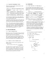
2.3,3 MAXIMUM PROGRAMMABLE VALUE Maximum programmable values of move com- mand are shown below. Table 2.3.3 Maximum Programmable Values In incremental programming, input values and the accumulative value must not exceed the max- imum programmable value. In absolute programming, input values and move amount of each axis specified by the inputs must not exceed the maximum programmable value. Note: The machine may not function properly if a move command over the maximum program- mable value is given. The above maximum pro- grammable values also apply to distance com- mand addresses I, J, K (R, QF...
Open the catalog to page 13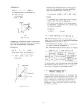
In the above case, the feedrate is: Values of F command at linear interpolation represent the tangential feedrate when three axes are simultaneously controlled. In the above case, the feedrate is: Values of F command at linear interpolation represent the tangential feedrate when four axes are simultaneously controlled . • A command "F0" cause data errors and the alarm code "15" will be displayed. • Any minus value should not be specified for F commands. If specified, the machine will The following feed function may be adopted in place of the feed function A described above when • Commanding tool...
Open the catalog to page 14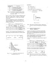
Note: For details of these G codes, refer to 2. 14. 19 Feed Function Designa- Since F code is modal, the code is effective until the next F code is given. However, whenG94/ G95 are switched over, F code must be desig- nated again. After the designation of G95, the feedrate-of- tool per spindle-revolution can be given by 4 digits following F. The command range of the Table 2,5.3.1 F Code (mm/rev-A) However, the programming of feedrate is re- stricted by the spindle speed (S) as shown below. In the above case, the feedrate is: Note- When G94 command is given, feedrate in mm per minute can be given...
Open the catalog to page 15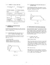
2.5.5 SUMMARY OF FEED FUNCTION CUTTING FEED In the following operation, the pattern of auto- matic acceleration and deceleration is exponen- Acceleration and deceleration for rapid traverse and for cutting feed are automatically performed without programming. RAPID TRAVERSE AND MANUAL FEED In the following operation, the pattern of auto- matic acceleration and deceleration is linear. • Manual rapid traverse (RAPID) - Manual continuous feeding (.JOG) ■ Manual HANDLE feeding (HANDLE) The miscellaneous function is specified with the address M and two digits. The function of each chine, except for...
Open the catalog to page 16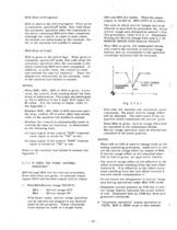
M02 is used at.the end of program. When given in automatic operation^ mode, this code stops the automatic operation after the commands in the block containing M02 have been completed. Although the control is reset in most cases, the details are determined by the machine. Re- fer to the machine tool builder's manual. M30 is given at the end of tape. .When given in - automatic operation# mode, this code stops the automatic operation after the commands in the block containing M30 have been completed. In addition, in most cases, the-control is reset and rewinds the tape (or memory).' Since the details...
Open the catalog to page 17All Yaskawa America, Inc. - Drives & Motion Division catalogs and technical brochures
 U1000
U100017 Pages
 MV1000NEMA 3R
5 Pages
 MV1000
13 Pages
 SG400
SG4002 Pages
 GP7 AND GP8
2 Pages
 INTEGRATED SOLUTIONS
11 Pages
 SIGMA TRAC II
9 Pages
 R1000
R100011 Pages
 iQPUMP AC DRIVE
13 Pages
 FP605
FP60515 Pages
 iQrise
2 Pages
 HV600
HV60019 Pages
 MACHINE CONTROL PRODUCTS
21 Pages
 D1000
D10002 Pages
 GA500
GA5009 Pages
 AC DRIVE SOFTWARE TOOLS
8 Pages
 YASKAWA AC Drive-L1000A
524 Pages
 1000 Series Low Voltage
15 Pages
 Yaskawa IEC Robot Control
5 Pages
 Yaskawa Type 3R Package
6 Pages
 Sigma SD
60 Pages
 GA800
GA8002 Pages
 MicroMax Marathon AC Motors
2 Pages
 L1000A
2 Pages
 BlackMax Marathon AC Motors
2 Pages
 BlueMax Marathon AC Motors
4 Pages
 NEMA Premium Efficiency XRI
2 Pages
 Yaskawa AC Drives PLC
2 Pages
 Deming Award
2 Pages
 SigmaLogic7 Compact
2 Pages
 Single Phase Converter
2 Pages
 Sigma-7 Servo Systems
4 Pages
 Z1000 Family of Drives Catalog
28 Pages
 iQpump Family Catalog
20 Pages
 Z1000 Bypass
2 Pages
 Z1000 Drive, 3HP to 500HP
2 Pages
 IEC - Comm Toolbox
2 Pages
 MP3200iec
2 Pages
 P1000 Catalog
52 Pages
 SGMMV
SGMMV20 Pages
 Bestact
64 Pages
 Sigma II Servo Catalog
202 Pages
 Sigma-5 Series Product Catalog
357 Pages
 A1000 Catalog
58 Pages
 LEGEND-MC (SMC-3010)
2 Pages
 YASNAG 2000G
58 Pages
 variable frequency drives
7 Pages
 Sigma-5 Servo Family
8 Pages
 Junma Series Servo
12 Pages


Archived catalogs
 Flyer Yaskawa Factory Repair
2 Pages


- Electromotor
- Synchronous motor
- Industrial robot
- Alternating current motor
- Electric gearmotor
- Automation software solution
- Digital I/O
- Electromotor for industrial applications
- Windows software
- Real-time software
- Proximity switch
- Three-phase motor
- Articulated robot
- IO module
- 6-axis robot
- Servo-motor
- Switching relay
- Analog I/O
- High-efficiency electromotor
- Digital IO module